Ryobi GD201 Quick Reference Guide
Ryobi GD201 Manual
 |
View all Ryobi GD201 manuals
Add to My Manuals
Save this manual to your list of manuals |
Ryobi GD201 manual content summary:
- Ryobi GD201 | Quick Reference Guide - Page 1
Reference Guide is not a substitute for reading the operator's manual. To reduce the risk of injury or death, user must read and understand operator's manual before installing or using this product. All page references refer to the operator's manual. ASSEMBLY 1 Check the condition of the door and
-
 1
1
 |
 |
991000809
6-23-16 (REV:03)
WARNING:
This Quick Reference Guide is not a substitute for reading the operator’s manual. To
reduce the risk of injury or death, user must read and understand operator’s manual
before installing or using this product. All page references refer to the operator’s manual.
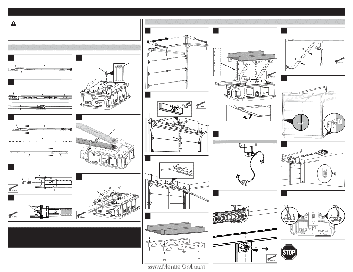
ASSEMBLY
INSTALLATION
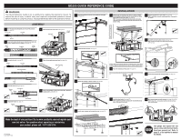
GD200 QUICK REFERENCE GUIDE
Make the most of your purchase! Go to www.ryobitools.com and register your
new tool online. For questions about operating or maintaining
your product, please call, 1-877-205-5714.
Insert outer trolley into the end rail. Slide the inner and outer
trolley’s together until they engage.
(See page 16).
Assemble the rails
(see page 16).
Pull the front pulley through the end rail and into a sleeve.
(see page 16).
Install the front brace
(see page 17).
2
3
4
Place sprocket onto power head
(see page 18).
Adjust belt tension
(see page 18).
Place rail assembly onto power head
(see page 19).
Secure rail assembly to power head. Raise Wi-Fi antenna to
upright position.
(See page 19).
Check the condition of the door and identify the spring type
(see page 21).
Measure and cut mounting straps that are a half inch longer
than the distance between the header bracket and the ceiling.
Mount power head to the ceiling
(see page 26).
NOTE: The proper configuration and placement of mounting
straps will vary based on the design and construction of your
garage ceiling.
Remove tape and position RF antenna beneath the garage door opener
for better signal reception between your opener and the outdoor keypad.
The garage door opener will not
open or close until the travel limits
have been properly set. Refer to
page 41 of the operator’s manual
for details.
Install indoor keypad and entrapment label
(see page 33).
Attach the emergency release rope
(see page 27).
Install the header bracket
(see page 23).
Install the door bracket
(see page 27).
NOTE: Installation varies for single panel and wooden garage
doors. See page 28 for details.
Wire indoor keypad and safety sensors
(see pages 32 and 33).
NOTE: Strip 1/2 in. of insulation from the ends of each wire
prior to installation.
Attach rail assembly to header bracket
(see page 24).
Install center brackets (not included) to joists
(see page 26).
1
6
5
7
8
1
5
8
9
10
11
6
2
7
3
4
Connect door bracket to outer trolley
(see page 29).
NOTE: Installation varies for single panel doors. See page 30
for details.
Assemble and install safety sensors
(see page 31).
Align sensors until they are directly facing each other
(see page 38).
End Rail
End Rail
End Rail
Intermediate Rail
Rail Assembly
Front Pulley
Sleeve
Sleeve
Sleeve
Outer
Trolley
Inner
Trolley
Front
Rail
Tension
Nut
Tension
Nut
Spring
Front Brace
Front Pulley
Nut
Bracket
Sprocket
Round
Side