Samsung PPM63H3 Service Manual
Samsung PPM63H3 Manual
 |
View all Samsung PPM63H3 manuals
Add to My Manuals
Save this manual to your list of manuals |
Samsung PPM63H3 manual content summary:
- Samsung PPM63H3 | Service Manual - Page 1
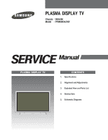
PLASMA DISPLAY TV Chassis : D63A(N) Model : PPM63H3X/XSF SERVICE Manual PLASMA DISPLAY TV CONTENTS 1. Specifications 2. Alignment and Adjustments 3. Exploded View and Parts List 4. Service Item 5. Schematic Diagrams - Samsung PPM63H3 | Service Manual - Page 2
ELECTRONICS This Service Manual is a property of Samsung Electronics Co.,Ltd. Any unauthorized use of Manual can be punished under applicable International and/or domestic law. © Samsung Electronics Co., Ltd. MAY. 2004 Printed in Korea AA82-01672A - Samsung PPM63H3 | Service Manual - Page 3
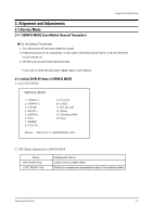
off and set to stand-by mode. 2. Press the buttons of the transmitter in this order; Info-Menu-Mute-Power or Mute-1-8-Power to turn the set on. 3. The set turns on and enters service mode. * If you fail to enter service mode, repeat steps 1 and 2 above. 2-1-2 Initial DISPLAY State of SERVICE MODE - Samsung PPM63H3 | Service Manual - Page 4
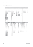
00 PIP B BRIGHTNESS 00 00 PIP FILTER IC 00 00 PIP FILTER ML 00 50 PIP FILTER MR 00 50 PIP FILTER UC 00 50 2-2 Samsung Electronics - Samsung PPM63H3 | Service Manual - Page 5
54/79/54 54/34/54 54/75/54 PC OFF CXA2151 GAIN SEL 01 CB GAIN 07 CR GAIN 07 Y GAI N 01 HFREQ 00 Samsung Electronics 2-3 - Samsung PPM63H3 | Service Manual - Page 6
130 130 130 130 B Gain 120 Logic R Cutoff 232 105 105 97 02 02 00 G Cutoff 00 00 00 00 B Cutoff 252 243 243 254 2-4 Samsung Electronics - Samsung PPM63H3 | Service Manual - Page 7
❈ Thus, Micom saves the W/B data separately for each memory mode of the block (See the block diagram given below) during W/B adjustment. Samsung Electronics Micom can memorize the four modes separately. However, under the current adjustment guidelines, DTV and PC are memorized with the same value - Samsung PPM63H3 | Service Manual - Page 8
295 25 31.5 20.0 285 285 285 295 295 295 0.8 0.9 0.8 Pattern Used in Adjustment : 10 Steps Gray scale pattern VIDEO 280 295 31.5 285 300 0.9 2-6 Samsung Electronics - Samsung PPM63H3 | Service Manual - Page 9
D5V CN851B CN802 CN803 CN852B CN801 OUTPUT VSCAN VS VSET VE VA D5V A6V Voltage See the labels attached on the base chassis. +5V +6V Samsung Electronics 2-7 - Samsung PPM63H3 | Service Manual - Page 10
MEMO 2-8 Samsung Electronics - Samsung PPM63H3 | Service Manual - Page 11
4. Service Item 4-1 Assy Board & Part List for Service Electrical Parts List Samsung Electronics 4-1 - Samsung PPM63H3 | Service Manual - Page 12
ASSY PCB MISC-ANALOG ASSY PCB MISC-CONTROL FAN-ASSY SCREEN-EMI,FILTER(GLASS) REMOCON S/W DRIVER (MDC S/W) MANUAL USERS CBF POWER CORD CODE BN68-00491A 3903-000082 SPECIFICATION ASSY PDP P-MODULE 63 INCH ,D54A,HD,NTSC,PAL,63 INCH PPM63H3,D63A,NEWTON VMB PPM63H3 24 SYNCMASTER,PIVOT,SAMSUNG PPM42S3/50H3/ - Samsung PPM63H3 | Service Manual - Page 13
;TM76,D61A,42,G6148,PPM42S3,EX 1 ASSY PCB MISC-DIGITAL;PPM63H3,D63A,NEWTO 1 ASSY PCB MISC-ANALOG;PPM63H3,D63A,VMB,SH 1 ASSY PCB MISC-CONTROL;SPD-63P3H,D57A,ALE 1 ASSY PDP P-SMPS;,D54A,HD,NTSC,PAL,63 INC 1 ASSY PDP P-SMPS,DC;,D54A,HD,NTSC,PAL,63 1 ASSY COVER P-BACK SUB;63P3 VMB,AL T1 - Samsung PPM63H3 | Service Manual - Page 14
MEMO 4-4 Samsung Electronics - Samsung PPM63H3 | Service Manual - Page 15
PPM63H3X/XSF Yon can search for the updated part code through ITSELF web site. URL:http://itself.sec.samsung.co.kr Samsung Description;Specification Q'ty CONTROL;P3,ABS,HB,WP1000 1 WINDOW-REMOTE;42P3S,PMMA,,,,,,CLEAR 1 ASSY PCB MISC-CONTROL PPM63H3,D63A,NEWTO 1 ASSY PCB MISC-ANALOG;PPM63H3 - Samsung PPM63H3 | Service Manual - Page 16
5. Schematic Diagrams 5-1 ANALOG 1 Analog - Digital Board Connector This Document can not be used without Samsung's authorization. S-Video Video IN Video/S-Video Sound COMPONENT1 TP01 TP03 TP02 CXA2151Q IC103 Schematic Diagrams TP01 TP02 TP03 Samsung Electronics 5-1 - Samsung PPM63H3 | Service Manual - Page 17
Schematic Diagrams 5-2 ANALOG 2 This Document can not be used without Samsung's authorization. 3D COMB FILTER R246 TILT SENSOR R247 FAN PART To DC FAN 50" 5-2 Samsung Electronics - Samsung PPM63H3 | Service Manual - Page 18
5-3 ANALOG 3 TP05 TP04 TP06 TP07 MONITOR OUT VIDEO MONITOR OUT SOUND Samsung Electronics From SMPS Board Schematic Diagrams TP04 TP05 TP06 TP07 External Speaker This Document can not be used without Samsung's authorization. 5-3 - Samsung PPM63H3 | Service Manual - Page 19
Schematic Diagrams 5-4 CONTROL This Document can not be used without Samsung's authorization. AA32-00013B 5-4 Samsung Electronics - Samsung PPM63H3 | Service Manual - Page 20
5-5 SMPS 1 This Document can not be used without Samsung's authorization. Samsung Electronics Schematic Diagrams 5-5 - Samsung PPM63H3 | Service Manual - Page 21
Schematic Diagrams 5-6 SMPS 2 This Document can not be used without Samsung's authorization. 5-6 Samsung Electronics - Samsung PPM63H3 | Service Manual - Page 22
5-7 SMPS 3 This Document can not be used without Samsung's authorization. Samsung Electronics Schematic Diagrams 5-7 - Samsung PPM63H3 | Service Manual - Page 23
Schematic Diagrams 5-8 SMPS 4 This Document can not be used without Samsung's authorization. 5-8 Samsung Electronics - Samsung PPM63H3 | Service Manual - Page 24
5-9 SMPS 5 This Document can not be used without Samsung's authorization. Samsung Electronics Schematic Diagrams 5-9 - Samsung PPM63H3 | Service Manual - Page 25
Schematic Diagrams 5-10 SMPS 6 This Document can not be used without Samsung's authorization. 5-10 Samsung Electronics - Samsung PPM63H3 | Service Manual - Page 26
5-11 SMPS 7 This Document can not be used without Samsung's authorization. Samsung Electronics Schematic Diagrams 5-11 - Samsung PPM63H3 | Service Manual - Page 27
Schematic Diagrams 5-12 DIGITAL 1 This Document can not be used without Samsung's authorization. Analog - Digital board Connector PC(D-SUB&DVI) SOUND 5-12 42 SD 42 HD 50,63 HD TP08 TP09 TP10 TP08 TP09 TP10 Samsung Electronics - Samsung PPM63H3 | Service Manual - Page 28
5-13 DIGITAL 2 This Document can not be used without Samsung's authorization. PC D-SUB BNC Connector ANALOG EDID EPROM From SMPS board TP23 TP24 TP22 TP21 TP20 Samsung Electronics Schematic Diagrams TP20 TP21 TP22 TP23 TP24 5-13 - Samsung PPM63H3 | Service Manual - Page 29
Schematic Diagrams 5-14 DIGITAL 3 This Document can not be used without Samsung's authorization. 5-14 Samsung Electronics - Samsung PPM63H3 | Service Manual - Page 30
5-15 DIGITAL 4 This Document can not be used without Samsung's authorization. DVI Connector DIGITAL EDID EPROM Samsung Electronics Schematic Diagrams 5-15 - Samsung PPM63H3 | Service Manual - Page 31
5-16 DIGITAL 5 This Document can not be used without Samsung's authorization. Samsung Electronics TP11 TP12 TP13 TP14 TP19 TP18 TP15 TP16 TP17 TP18 Schematic Diagrams TP11 TP19 TP12 TP13 TP14 TP15 TP16 TP17 5-16 - Samsung PPM63H3 | Service Manual - Page 32
Schematic Diagrams 5-17 DIGITAL 6 This Document can not be used without Samsung's authorization. USER EPROM (256K) TP26 TP25 B12 : 1204-002105 RS232C OUT 5-17 RS232C IN Flash Memory Download Flash Memory From Remote Control board TP25 TP26 Samsung Electronics - Samsung PPM63H3 | Service Manual - Page 33
5-18 DIGITAL 7 This Document can not be used without Samsung's authorization. TP27 Schematic Diagrams TP28 TP27 TP28 Samsung Electronics 5-18 - Samsung PPM63H3 | Service Manual - Page 34
Schematic Diagrams 5-19 DIGITAL 8 This Document can not be used without Samsung's authorization. 5-19 LVDS Connector Samsung Electronics - Samsung PPM63H3 | Service Manual - Page 35
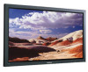
Specifications MODEL Dimensions Display Weight Display Screen Size Voltage Power Consumption Number of Pixels External Control AUDIO Input AUDIO Output VIDEO Input VIDEO Output PPM63H3 1503.4(W) x 89(D) x 893.8(H) mm / 59.15(W) x 3.5(D) x 35.19(H) inches 69 Kg (without stand) 63 - Samsung PPM63H3 | Service Manual - Page 36
MEMO 1-2 Samsung Electronics
-
 1
1 -
 2
2 -
 3
3 -
 4
4 -
 5
5 -
 6
6 -
 7
7 -
8
-
9
-
10
-
11
-
12
-
13
-
14
-
15
-
16
-
17
-
18
-
19
-
20
-
21
-
22
-
23
-
24
-
25
-
26
-
27
-
28
-
29
-
30
-
31
-
32
-
33
-
34
-
35
-
36
 |
 |
PLASMA DISPLAY TV
Chassis
: D63A(N)
Model
: PPM63H3X/XSF
PLASMA DISPLAY TV
CONTENTS
1.
2.
3.
4.
5.
Specifications
Alignment and Adjustments
Exploded View and Parts List
Service Item
Schematic Diagrams
SERVICE
Manual