Sanyo PLC-XP40 Owners Manual
Sanyo PLC-XP40 - XGA LCD Projector Manual
 |
View all Sanyo PLC-XP40 manuals
Add to My Manuals
Save this manual to your list of manuals |
Sanyo PLC-XP40 manual content summary:
- Sanyo PLC-XP40 | Owners Manual - Page 1
Multimedia Projector MODEL PLC-XP40 Owner's Manual - Sanyo PLC-XP40 | Owners Manual - Page 2
operate improperly, read this manual again, check operations and cable connections and try the solutions in the "Trouble-shooting" section of the end of this booklet. If the problem still persists, contact the sales dealer where you purchased the projector or the service center. SAFETY PRECAUTIONS - Sanyo PLC-XP40 | Owners Manual - Page 3
the projector. Wall or shelf mounting should follow the manufacturer's instructions, and should use a mounting kit projector exhibits a distinct change in performance-this indicates a need for service. When replacement parts are required, be sure the service technician has used replacement parts - Sanyo PLC-XP40 | Owners Manual - Page 4
instructions. If such changes or modifications should be made, you could be required to stop operation of the equipment. Model Number Trade Name Responsible party Address Telephone No. : PLC-XP40 : Sanyo : SANYO available from the Parts Department indicated in your User Instructions. If the plug - Sanyo PLC-XP40 | Owners Manual - Page 5
OF REMOTE CONTROL 14 SETTING 35 LASER POINTER FUNCTION 14 REMOTE CONTROL BATTERIES INSTALLATION 15 TOP CONTROLS AND PROJECTOR 19 CLEANING PROJECTION LENS 38 ADJUSTING SCREEN ZOOM ADJUSTMENT FOCUS ADJUSTMENT 20 20 20 LAMP REPLACEMENT LAMP REPLACE COUNTER TROUBLESHOOTING 39 39 40 LENS - Sanyo PLC-XP40 | Owners Manual - Page 6
has Wireless Mouse function for a connected computer. This function enables you to operate both projector and computer with Remote Control Unit only. x Multilanguage Menu Display Operation menu is displayed in; English, German, French, Italian, Spanish, Portuguese, Dutch, Swedish, Chinese, Korean - Sanyo PLC-XP40 | Owners Manual - Page 7
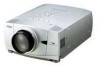
PREPARATION NAME OF EACH PART OF PROJECTOR FRONT OF CABINET TOP CONTROLS AND INDICATORS PROJECTION LENS AIR INTAKE VENT LENS COVER SPEAKERS INFRARED REMOTE RECEIVER BACK OF CABINET EXHAUST VENT POWER CORD CONNECTOR INFRARED REMOTE RECEIVER HOT AIR EXHAUSTED ! Air blown from exhaust vent is - Sanyo PLC-XP40 | Owners Manual - Page 8
plug into any other type of power system. Consult your authorized dealer or service station if you are not sure of type of power supply being in use. Connect a projector with a peripheral equipment before turning a projector on. (Refer to pages 11 ~ 13 for connection.) CAUTION For safety, unplug AC - Sanyo PLC-XP40 | Owners Manual - Page 9
designed to project on a flat projection surface. q Projector can be focused from 4.6' (1.4m) ~ 47.3' .5' (9.0m) 35.4' (10.8m) 47.3' (14.4m) LENS SHIFT ADJUSTMENT Projection lens can be moved up and down with motor-driven lens shift function. This function makes it easy to provide projected image - Sanyo PLC-XP40 | Owners Manual - Page 10
using Menu Operation. (Refer to P 20 and 35.) ADJUSTABLE FEET MOVING PROJECTOR Use Carry Handle when moving a Projector. When moving a projector, replace lens cover and retract feet to prevent damage to lens and cabinet. When this projector is not in use for an extended period, put it into case - Sanyo PLC-XP40 | Owners Manual - Page 11
3 R/C JACK When using Wired/Wireless Remote Control Unit as Wired Remote Control, Connect Wired Remote Control Unit to this jack with Remote Control Cable (supplied). CONTROL PORT CONNECTOR When controlling computer with Remote Control Unit of this projector, connect mouse port of your personal - Sanyo PLC-XP40 | Owners Manual - Page 12
VIDEO/Y Cb/Pb Cr/Pr INPUT 2 VIDEO/Y Cb/Pb Cr/Pr R-AUDIO-L S-VIDEO (MONO) INPUT 3 Terminals of a Projector Use one of these Control Cables corresponding with terminal of your computer. CONTROL PORT 12 x MAC ADAPTER Set switches as shown in table below depending on RESOLU- ON TION MODE that - Sanyo PLC-XP40 | Owners Manual - Page 13
EQUIPMENT Cables used for connection (✽ = Cable is not supplied with this projector.) • Video Cable (RCA x 1 or RCA x 3) ✽ • - Cr/Pr AUDIO IN S-VIDEO ANALOG INPUT 1 DIGITAL(DVI-D) R/C JACK AUDIO 1 USB RESET CONTROL PORT AUDIO 2 G B R H/V V VIDEO/Y Cb/Pb Cr/Pr INPUT 2 VIDEO/Y Cb/Pb - Sanyo PLC-XP40 | Owners Manual - Page 14
operation. (P17, 18) MUTE D.ZOOM INPUT MENU ALL-OFF SWITCH When using Remote Control Unit, turn this switch to "ON." And turn it to "ALL OFF" and press it again. LASER LENS SHIFT KEYSTONE NO SHOW FREEZE AUTO PC ADJ. IMAGE P-TIMER POWER ON-OFF BUTTON Used to turn projector on or off. (P19) - Sanyo PLC-XP40 | Owners Manual - Page 15
ZOOM +/- mode and resize image. (P29) LENS SHIFT BUTTON Used to select LENS SHIFT function. (P20) FREEZE BUTTON Used to freeze picture. (P21) IMAGE BUTTON Used to select image level. (P27, 32) Operating Range Point Remote Control Unit toward projector (Receiver Window) whenever pressing any button - Sanyo PLC-XP40 | Owners Manual - Page 16
BEFORE OPERATION TOP CONTROLS AND INDICATORS This projector has CONTROL BUTTONS (TOP CONTROLS) and INDICATORS on its top. LAMP REPLACE INDICATOR Turns to yellow when life of projection lamp draws to an end. (P39) WARNING TEMP. INDICATOR Flashes red when internal projector temperature is too high. - Sanyo PLC-XP40 | Owners Manual - Page 17
HOW TO OPERATE ON-SCREEN MENU You can control and adjust this projector through ON-SCREEN MENU. Refer to following pages to operate each adjustment on ON-SCREEN MENU. 1 DISPLAY MENU Press MENU button to display ON-SCREEN MENU. WIRELESS REMOTE CONTROL POINT BUTTON Used to move Pointer UP/ DOWN - Sanyo PLC-XP40 | Owners Manual - Page 18
Press MENU BUTTON while connecting to PC input source. GUIDE WINDOW Shows selected item of ONSCREEN MENU. PC Wide / Digital zoom +/-] (Refer to P29) SETTING MENU Used to change settings of projector or reset Lamp Replace Counter. (Refer to P35,-37) INPUT MENU Used to select input source (Input - Sanyo PLC-XP40 | Owners Manual - Page 19
PROJECTOR 1 Press POWER ON-OFF button on Top Control or on Remote Control Unit, and a message "Power off?" appears on a screen. 2 Press POWER ON-OFF button again to turn off projector. LAMP Indicator lights bright and READY Indicator turns off. After projector projector - Sanyo PLC-XP40 | Owners Manual - Page 20
image by pressing FOCUS v/w button or POINT UP/DOWN button(s) . Focus Message disappears after 4 seconds. LENS SHIFT ADJUSTMENT 1 Press LENS SHIFT button on Top Control or on Remote Control Unit. Message "Lens shift" is displayed. 2 Press POINT UP button to move image up, press POINT DOWN button - Sanyo PLC-XP40 | Owners Manual - Page 21
button again or press any other button except POINT / SELECT / RIGHT CLICK / P-TIMER / LASER button. NO SHOW FUNCTION Press NO SHOW button on Remote Control Unit to black out image. To restore to normal, press NO SHOW button again or press any other button except POINT / SELECT / RIGHT CLICK - Sanyo PLC-XP40 | Owners Manual - Page 22
COMPUTER INPUT SELECTING INPUT SOURCE DIRECT OPERATION Choose Computer by pressing INPUT button on Top Control or on Remote Control Unit. If projector cannot reproduce proper image, select correct input source through MENU OPERATION (see below). INPUT button INPUT 1 INPUT 2 INPUT 3 MENU - Sanyo PLC-XP40 | Owners Manual - Page 23
on SYSTEM Menu icon. When image is not provided properly, manual adjustment is required. (Refer to P24 and 25.) There is no signal input from computer. Make sure connection of computer and a projector is set correctly. (Refer to TROUBLESHOOTING on page 40.) PC SYSTEM MENU PC SYSTEM Menu icon - Sanyo PLC-XP40 | Owners Manual - Page 24
cannot reproduce a proper image and image may be recognized as a flickering picture, a non-synchronized picture, a non-centered picture or a skewed picture. This projector has a Manual PC Adjustment to enable you to precisely adjust several parameters to match with those special signal formats. This - Sanyo PLC-XP40 | Owners Manual - Page 25
SELECT button at Display area icon and Display area dialog box appears. Display area Display area V Adjustment of vertical area displayed with this projector. Press POINT LEFT/RIGHT button(s) to decrease/increase value and then press SELECT button. Full screen Press POINT LEFT/RIGHT button(s) to - Sanyo PLC-XP40 | Owners Manual - Page 26
COMPUTER INPUT COMPATIBLE COMPUTER SPECIFICATIONS Basically this projector can accept a signal from all computers with V, H-Frequency mentioned below and less than 160 MHz of .40 50.00 50.00 63.37 76.97 61.85 46.43 63.79 75.00 80.00 45.00 33.75 33.75 V-Freq. (Hz) 77.07 75.70 43.48 58.20 58.30 72 - Sanyo PLC-XP40 | Owners Manual - Page 27
Image 2, Image 3 and Image 4 by pressing IMAGE button on Top Control or on Remote Control Unit. Standard Normal picture level preset on this projector. Real Picture level with improved halftone for graphics. IMAGE 1~4 User preset picture adjustment in IMAGE ADJUST Menu (P28). IMAGE button Standard - Sanyo PLC-XP40 | Owners Manual - Page 28
0 to 63.) Gamma Press either POINT LEFT button or POINT RIGHT button to obtain better balance of contrast. (From 0 to 15.) 3 Store To store manually preset image, move a red frame pointer to Store icon and press SELECT button. Image Level Menu will appear. Move a red frame pointer to Image 1 to - Sanyo PLC-XP40 | Owners Manual - Page 29
image size is larger than screen size (1024 x 768), this projector enters "Digital zoom +" mode automatically. Wide Provides image to fit size. A projected image can be also expanded by pressing D.ZOOM v button on Remote Control Unit. NOTE q True and Digital zoom +/- cannot be operated when "RGB", - Sanyo PLC-XP40 | Owners Manual - Page 30
VIDEO INPUT SELECTING INPUT SOURCE WHEN SELECT INPUT 2 (5 BNC INPUT JACKS ) When connecting to those equipment, select a type of Video INPUT MENU source in SOURCE SELECT Menu. 1 Press MENU button and ON-SCREEN MENU will appear. Press POINT LEFT/RIGHT button to move a red frame pointer to INPUT - Sanyo PLC-XP40 | Owners Manual - Page 31
Video signal, and adjusts itself to optimize its performance. When Video System is 1035i or 1080i, select system manually first. COMPONENT VIDEO SIGNAL FORMAT If projector cannot reproduce proper video image, it is necessary to select a specific component video signal format among 480i, 575i - Sanyo PLC-XP40 | Owners Manual - Page 32
1, Image 2, Image 3 and Image 4 by pressing IMAGE button on Top Control or on Remote Control Unit. Standard Normal picture level preset on this projector. Cinema Picture level adjusted for picture with fine tone. IMAGE 1~4 User preset picture adjustment in IMAGE ADJUST Menu (P34). IMAGE button - Sanyo PLC-XP40 | Owners Manual - Page 33
.) Noise reduction Press POINT LEFT/RIGHT button(s) to change noise reduction mode. Dialog box display is changed to "On to reduce noise (rough parts) of image. Press POINT LEFT/RIGHT button(s) again, to change noise reduction mode to off. Progressive scan Press POINT LEFT/RIGHT button(s) to change - Sanyo PLC-XP40 | Owners Manual - Page 34
. Image Level Menu Move a red frame pointer to image icon to be set and then press SELECT button. Store icon PICTURE SCREEN ADJUSTMENT This projector has a picture screen resize function, which enables you to display desirable image size. 1 Press MENU button and ON-SCREEN MENU will appear. Press - Sanyo PLC-XP40 | Owners Manual - Page 35
When this function is "On," picture is top / bottom and left / right reversed. This function is used to project image from a ceiling mounted projector. Ceiling function Rear When this function is "On," picture is left / right reversed. This function is used to project image to a rear projection - Sanyo PLC-XP40 | Owners Manual - Page 36
again (Power Management mode). In this Power Management mode, Projection Lamp is automatically turned on when input signal connected or projector is operated with any button on Top Control or on Remote Control Unit again. Time left until Lamp off. Press SELECT button at this icon to display other - Sanyo PLC-XP40 | Owners Manual - Page 37
Select " " when controlling a computer with Remote Control of this projector. Projector mode Select " " when controlling a projector with computer. NOTE: Before you control a projector by computer, install USB driver (optionally sold parts) and set up computer following instruction in USB - Sanyo PLC-XP40 | Owners Manual - Page 38
operate a projector with Air Filter removed. Dust may accumulate on LCD Panel and Projection Mirror degrading picture quality. Do not put small parts into Air service station for proper cleaning. CLEANING PROJECTION LENS Follow these steps to clean Projection Lens: 1 Apply a non-abrasive camera lens - Sanyo PLC-XP40 | Owners Manual - Page 39
information to dealer. q Model No. of your projector : PLC-XP40 q Replacement Lamp Type No. : POA-LMP38 (Service Parts No. 610 293 5868) LAMP REPLACE COUNTER Be sure to reset Lamp Replace Counter when Lamp Assembly is replaced. When Lamp Replace Counter is reset, LAMP REPLACE Indicator stops - Sanyo PLC-XP40 | Owners Manual - Page 40
your computer. 5. If an image still does not appear, unplug a projector from your computer and check your computer monitor's display. Problem may be with your graphics controller rather than with a projector. (When you reconnect a projector, be sure to turn computer and monitor off before you power - Sanyo PLC-XP40 | Owners Manual - Page 41
problems yourself. If a projector fails to work properly, see "TROUBLESHOOTING" section on page 40, 41. To correct failure, try "Solutions". If after following all operating instructions, you find that service is necessary, contact Sanyo Service Station or store where you purchased unit. Give model - Sanyo PLC-XP40 | Owners Manual - Page 42
: 1mW / Wave length : 650±20nm) Owner's Manual AC Power Cord Wireless/Wired Remote Control Transmitter and Batteries Remote Control Cable VGA Cable MAC/VGA Adapter 3 Types Control Cable (For PS/2, Serial and ADB port) Protective Dust Cover Lens Cover q Specifications are subject to change without - Sanyo PLC-XP40 | Owners Manual - Page 43
6 DDC Clock 14 +5V Power 22 T.M.D.S. Clock Shield 7 DDC Data 15 Ground (for +5V) 23 T.M.D.S. Clock+ 8 No Connect 16 Hot Plug Detect 24 T.M.D.S. Clock- CONTROL PORT CONNECTOR Terminal : Mini DIN 8-PIN Connect control port (PS/2, Serial or ADB port) on your computer to this connector with - Sanyo PLC-XP40 | Owners Manual - Page 44
Printed in Japan Part No. 610 293 5264 (1AA6P1P2866-- MB8A) SANYO Electric Co., Ltd
-
 1
1 -
 2
2 -
 3
3 -
 4
4 -
 5
5 -
 6
6 -
 7
7 -
8
-
9
-
10
-
11
-
12
-
13
-
14
-
15
-
16
-
17
-
18
-
19
-
20
-
21
-
22
-
23
-
24
-
25
-
26
-
27
-
28
-
29
-
30
-
31
-
32
-
33
-
34
-
35
-
36
-
37
-
38
-
39
-
40
-
41
-
42
-
43
-
44
 |
 |

Owner’s Manual
PLC-XP40
Multimedia Projector
MODEL