Sharp LC-20AV7U Service Manual
Sharp LC-20AV7U Manual
 |
View all Sharp LC-20AV7U manuals
Add to My Manuals
Save this manual to your list of manuals |
Sharp LC-20AV7U manual content summary:
- Sharp LC-20AV7U | Service Manual - Page 1
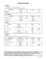
SERVICE MANUAL S37F3LC20AV7U LCD COLOR TELEVISION MODEL LC-20AV7U MODEL LC-20SH7U In the interests of user-safety (Required by safety regulations in some countries) the set should be restored to its original condition and only parts identical to those specified be used. CONTENTS Page SPECIFICATIONS - Sharp LC-20AV7U | Service Manual - Page 2
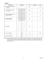
SPECIFICATIONS < TUNER > VHF/UHF Input : 75 ohm Unbal., F type Intermediate Freq. : Picture 45.75 MHz, Sound 41.25 MHz Description 1. Video S/N 2. Audio S/N Condition Unit 80dB dB 80dB dB Nominal ----- < LCD Description 1. Audio Output Power 2. Audio Distortion 3. 45/45 The LCD panel is - Sharp LC-20AV7U | Service Manual - Page 3
Lch Rch Unit Nominal Limit kHz --- >100 dBm --- -76/0 dB --- -6 dB --- 50 % --- - Sharp LC-20AV7U | Service Manual - Page 4
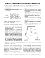
PRECAUTIONS A PRENDRE LORS DE LA REPARATION Ne peut effectuer la réparation qu' un technicien spécialisé qui s'est parfaitement accoutumé à toute vérification de sécurité et aux conseils suivants. AVERTISSEMENT 1. N'entreprendre aucune modification de tout circuit. C'est dangereux. 2. Débrancher le - Sharp LC-20AV7U | Service Manual - Page 5
attached on the PWBs and service manuals. For PWBs with Pb free shown. < Bottom View > Pin 1 Instructions for Connectors 1. When you connect or lead-free wire solder. Repairing with conventional lead wire solder heat-resistance temperature of parts may be exceeded, on and off the power of the bit as - Sharp LC-20AV7U | Service Manual - Page 6
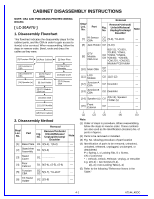
CABINET DISASSEMBLY INSTRUCTIONS NOTE: CBA AND PWB MEANS PRINTED WIRING BOARD. [ LC-20AV7U ] 1. Disassembly Flowchart This flowchart indicates the disassembly steps for the cabinet parts, and the CBA in order to gain access to item(s) to be serviced. When reassembling, follow the steps in reverse - Sharp LC-20AV7U | Service Manual - Page 7
[4] Rear Cabinet (S-5) (S-4) (S-4) (S-4) (S-4) (S-6) (S-4) (S-1) [3] Stand Cover [2] Stand Arm Assembly [1] Base Plate (S-3) (S-3) (S-2) (S-2) (S-2) Fig. D1 4-2 A7144_45DC - Sharp LC-20AV7U | Service Manual - Page 8
13] Junction-B CBA Speaker Holder (S-12) (S-7) [5] Function CBA (S-7) [11] LCD Module (S-12) Desolder [14] Speaker (S-13) (S-12) (S-12) [14 Holder [12] Junction-A CBA (S-13) (S-12) (S-8) (S-11) [6] Tilt Stand Holder (S-10) Module PCB Holder (S-11) (S-11) (S-11) [9] DTV Module - Sharp LC-20AV7U | Service Manual - Page 9
TV Cable Wiring Diagram Main CBA CN401 Function CBA CL1107 CN1301 To LCD Module CN1202 CN1201 To LCD Module CN402 Junction-A CBA CL801 To Speaker CN403 CN801 CN1302 CL1104 IR Sensor CBA CN62 CN61 CN102 CN101 CN802 Junction-B CBA CL802 DTV Module CBA - Sharp LC-20AV7U | Service Manual - Page 10
CBA Unit [2] Stand Arm Assembly [3] Stand Cover [10] Main CBA [11] LCD Module [13] Front Cabinet 4. Disassembly Method Removal Step/ Remove/*Unhook/ Loc. No. Part Fig. No. Unlock/Release/ Unplug/Unclamp/ Note Desolder [1] Base Plate D1 2(S-1), 7(S-2) --- [2] Stand Arm Assembly D1 - Sharp LC-20AV7U | Service Manual - Page 11
[4] Rear Cabinet (S-4) (S-4) (S-4) (S-5) (S-1) (S-4) [3] Stand Cover [2] Stand Arm Assembly [1] Base Plate (S-3) (S-3) (S-2) (S-2) (S-2) Fig. D1 4-6 A7144_45DC - Sharp LC-20AV7U | Service Manual - Page 12
Cabinet (S-6) [12] Speaker [5] Function CBA (S-7) (S-6) (S-7) [11] LCD Module (S-13) (S-12) [12] Speaker (S-9) (S-12) Washer [7] IR Sensor CBA (S-13) [10] Main CBA [8] Jack (S-12) Holder (S-11) (S-11) (S-12) (S-8) (S-11) [6] Tilt Stand Holder (S-10) Module PCB Holder (S-11 - Sharp LC-20AV7U | Service Manual - Page 13
TV Cable Wiring Diagram Main CBA CN401 Function CBA CL1107 CN1301 To LCD Module CN1202 CN1201 To LCD Module CN402 To Speaker CN403 CN801 CN1302 CL1104 IR Sensor CBA CN62 CN61 CN102 CN101 DTV Module CBA Unit CN802 To Speaker Fig. D3 4-8 A7144_45DC - Sharp LC-20AV7U | Service Manual - Page 14
Color, Dot Pattern, Gray Scale, Monoscope, Multi-Burst) 3. Remote control unit 4. Color Analyzer How to enter the service mode: Press [MENU] and [POWER] buttons on the TV unit simultaneously in the standby mode. 1. Initial Setting General: Enter Service mode. Set initial data as shown on table - Sharp LC-20AV7U | Service Manual - Page 15
value and "y" value are not within specification, adjust "CCOB(C/D2)" or "C-COR(C/D2)". Refer to "1. Initial Setting." 7. Turn the power off and on again. (Main power button on the TV unit.) L = 3 cm INPUT: WHITE 80%, 20% Color Analyzer Note: Use the service remote control unit 1. Operate the unit - Sharp LC-20AV7U | Service Manual - Page 16
), w/SETUP 7.5IRE M. EQ. Spec. Pattern Generator See below Figure White A position B position Black C position 1. Enter the Service mode. Then input above signal. 2. [RF/INPUT1] Press [MENU] button on the service remote control unit and press [1] on the service remote control (selecting "BRT - Sharp LC-20AV7U | Service Manual - Page 17
HOW TO INITIALIZE THE LCD TELEVISION 1. To enter the service mode, press [MENU] and [POWER] buttons on the TV unit simultaneously in the standby mode. 2. To initialize the LCD television, press [DISPLAY] button on the remote control unit. 3. Confirm "FF" indication on the upper right of the screen. - Sharp LC-20AV7U | Service Manual - Page 18
+9V is not output. 7-5 18 DTV-ON+1.8V is not output. 7-6 19 PANEL-6V is not output. 7-6 20 The key operation is not functioning. 7-6 21 No operation is possible from the remote control unit. 7-7 22 Picture does not appear normally. (Tuner input (Analog) / Video input/S-Video input) 7-8 23 - Sharp LC-20AV7U | Service Manual - Page 19
can be heard in the vicinity of power circuit. Check IC601,Q913,D909,D933 and their periphery, and service it if defective. Check if there approximately 35V voltage supplied to the cathode of D909? Yes Check if there is any leak or short-circuit on the loaded circuit, and service it if defective - Sharp LC-20AV7U | Service Manual - Page 20
cathode of D909? Yes No See FLOW CHART No.5 Check D928, R952 and their periphery circuit, and service it if defective. FLOW CHART NO.7 INV+22V is not output. Is approximately 22V voltage supplied to the cathode of D901? Yes Check if there is any leak or short-circuit on the loaded - Sharp LC-20AV7U | Service Manual - Page 21
the voltage of base on Q905 lower than the voltage of emitter on Q905 when turning the power on? Yes Replace Q905. FLOW CHART NO.11 AL+3.3V(D) is not output. Is approximately 6.8V voltage supplied to the cathode of D903? Yes Check Q902, D920 and their periphery circuit, and service it if defective - Sharp LC-20AV7U | Service Manual - Page 22
12V voltage supplied to the No cathode of D902? Yes Check if there is any leak or short-circuit on the loaded circuit and service it if supplied to the Yes collector of Q923? No Is the voltage of base on Q923 lower than the No voltage of emitter on Q923 when turning the power - Sharp LC-20AV7U | Service Manual - Page 23
NO.19 PANEL-6V is not output. Is approximately -6V voltage supplied to the No anode of D931? Yes Check if there is any leak or short-circuit on the loaded circuit and service it if defective. FLOW CHART NO.20 The key operation is not functioning. Are the contact point and installation - Sharp LC-20AV7U | Service Manual - Page 24
is activated? Yes Is the "L" pulse supplied to the Pin(3) of CN1302? No Yes Check IC1202 and the periphery circuit, and service it if defective. Check AL+3.3V(D) line and service it if defective. Replace the infrared remote control receiver (RV1142) or the remote control unit. Check the line - Sharp LC-20AV7U | Service Manual - Page 25
. Check the line between Pin(54) of IC1202 and Pin(20) of CN62, and service it if defective. Check the line between Pin(64) of IC1202 and Pin(19) of CN62, and service it if defective. Are the video signals outputted to the specific input terminal? Are the Y signals outputted to the Pin(75 - Sharp LC-20AV7U | Service Manual - Page 26
to the Pins(11,14) No of IC801? Yes Check SP801,SP802,JK801 and their periphery circuit, and service it if defective. FLOW CHART NO.26 Audio is not outputted normally. (Tuner input (Digital)) Are the DIF signals outputted to the Pins(11, 12) No of CN62? Yes Are the audio (L/R) signals - Sharp LC-20AV7U | Service Manual - Page 27
IC852? Yes Are the audio (L/R) signals outputted to the No Pins(11,14) of IC801? Yes Check SP801, SP802, JK801 and their periphery circuit, and service it if defective. Check the line between Pins(2,4,11,15) of IC852 and each Audio input terminals (JK704, JK705, JK709, JK710), and - Sharp LC-20AV7U | Service Manual - Page 28
CBA KEY SWITCH KEY SWITCH CN1302 3 REMOTE 4 P-ON-H CL1104 3 4 RV1142 REMOTE SENSOR Q1142 LED DRIVE D1142 POWER AL+3.3V(D) IR SENSOR CBA VCOM DTV-ON-H BACKLIGHT-SW P-ON-H VGH-H BACKLIGHT-ADJ TO LCD BLOCK DIAGRAM TO POWER SUPPLY BLOCK DIAGRAM TO LCD BACKLIGHT BLOCK DIAGRAM IF-MUTE INPUT - Sharp LC-20AV7U | Service Manual - Page 29
-2 Q707 Q708 Q709 VIDEO SIGNAL AUDIO SIGNAL MAIN CBA SIF TO AUDIO BLOCK DIAGRAM AFT-IN TO SYSTEM CONTROL BLOCK DIAGRAM RF-CVBS S-VIDEO-C TO LCD BLOCK DIAGRAM S-VIDEO-Y INPUT-0(INV) INPUT-1(INV) INPUT-2(INV) TO AUDIO BLOCK DIAGRAM VIDEO-Y VIDEO-Pb VIDEO-Pr VIDEO-IN1 TO - Sharp LC-20AV7U | Service Manual - Page 30
Marks Model Mark LC-20AV7U A LC-20SH7U B AUDIO SIGNAL OFFSET CANCEL WIDE BAND FILTER WIDE BAND RMS DET WIDE BAND EXPAND OFFSET CANCEL dBX DE-EMPH SPECTRAL EXPAND SPECTRAL FILTER SPECTRAL RMS DET L-CH 30 MATRIX AGC R-CH 29 8-3 JK1701 DIGITAL AUDIO-OUT TO DTV MODULE BLOCK DIAGRAM - Sharp LC-20AV7U | Service Manual - Page 31
XOUT-27MHz X281 25MHz OSC 4 XIN-25MHz 5 XOUT-25MHz DIGITAL SIGNAL PROCESS SYSTEM DECODER /VIDEO DECODER /VIDEO FORMAT CONVERTER /2D Q214 Q213 FLASH MEMORY I/F DATA BUS(0-15) *3 ADDRESS BUS(1-20) *4 DTV-Y DTV-Pr DTV-Pb TO LCD BLOCK DIAGRAM DTV-AUDIO(L) DTV-AUDIO(R) DTV-SPDIF TO AUDIO BLOCK - Sharp LC-20AV7U | Service Manual - Page 32
56 WF5 64 66 WF6 A/D Y A/D Pb A/D Pr R(ODD) G(ODD) LCD RGB SIGNAL PROCESS B(ODD) R(EVEN) G(EVEN) B(EVEN) TO SYSTEM CONTROL BLOCK ER(0) 5 ER(1) 4 ER(2) 3 ER(3) 2 ER(4) 1 ER(5) LCD MODULE CN1202 31 EG(0) 30 EG(1) 22 EG(2) 21 EG(3) 20 EG(4) 19 EG(5) 17 EB(0) 16 EB(1) 15 EB(2) 14 EB(3) - Sharp LC-20AV7U | Service Manual - Page 33
power supply circuit to fail. 4A/125V CAUTION ! : For continued protection against risk of fire, replace only with same type 4 A, 125V fuse. ATTENTION : Utiliser un fusible de rechange de même type de 4A, 125V. NOTE: The voltage for parts +22V BACKLIGHT-SW TO LCD BACKLIGHT BLOCK DIAGRAM TO SYSTEM - Sharp LC-20AV7U | Service Manual - Page 34
NOTE: CBA AND PWB MEANS PRINTED WIRING BOARD. TO POWER SUPPLY BLOCK DIAGRAM INV+22V Q401 SW+22V Q407 SWITCHING TO SYSTEM OVER VOLTAGE PROTECTOR CN402 1 2 BACK LIGHT Q442,443 OVER VOLTAGE PROTECTOR CN403 1 2 BACK LIGHT Q462,463 OVER VOLTAGE PROTECTOR LCD MODULE LCD Backlight Block Diagram - Sharp LC-20AV7U | Service Manual - Page 35
having such features are identified by the mark " # " in the schematic diagram and the parts list. Before replacing any of these components, read the parts list in this manual carefully. The use of substitute replacement parts that do not have the same safety characteristics as specified in the - Sharp LC-20AV7U | Service Manual - Page 36
Auto voltage selectable) power supply circuit is used in this unit. If repaired units, use only original replacement parts which are listed with their part numbers in the parts list section of the service manual. 4. Voltage indications on the schematics are as shown below: Plug the TV power - Sharp LC-20AV7U | Service Manual - Page 37
PRINTED WIRING BOARD. Comparison Chart of Models and Marks Model Mark LC-20AV7U A LC-20SH7U B MAIN 1/5 Ref No. 9 0 10 -6.2 11 0 12 1.2 13 0.7 14 0.5 15 0.7 16 1.3 17 1.1 18 0 19 1.2 20 0.9 21 0.7 22 0.8 23 0 24 0 25 0 26 0 27 0 28 2.1 29 0 30 1.3 31 - Sharp LC-20AV7U | Service Manual - Page 38
G-2 9-4 VOLTAGE CHART CN61 Pin No. Voltage 1 0 2 1.1 3 5.2 4 3.1 5 3.2 6 0 7 2.9 8 3.2 9 1.7 10 0.1 11 0 12 3.4 13 0 14 3.1 15 3.1 CN62 Pin No. 1 2 3 4 5 6 7 8 9 10 11 12 13 14 15 16 17 18 19 20 Voltage --3.3 0 3.4 2.6 1.9 --0 0 0 0 0 0 --2.6 2.6 0 ~ ~ ~ A7144SCM2 - Sharp LC-20AV7U | Service Manual - Page 39
3/5, Junction-A & Junction-B Schematic Diagram NOTE: CBA AND PWB MEANS PRINTED WIRING BOARD. Comparison Chart of Models and Marks Model Mark LC-20AV7U A LC-20SH7U B MAIN 3/5 Ref No. Position IC IC801 N-2 TRANSISTORS Q707 P-3 Q708 P-2 Q709 P-2 Q802 N-1 CONNECTORS CN801 N-3 CN802 - Sharp LC-20AV7U | Service Manual - Page 40
Main 4/5 Schematic Diagram NOTE: CBA AND PWB MEANS PRINTED WIRING BOARD. MAIN 4/5 Ref No. Position TRANSISTORS Q401 T-2 Q402 T-1 Q403 T-1 Q404 T-2 Q405 T-2 Q406 T-3 Q407 T-1 Q421 U-4 Q422 W-4 Q423 W-4 Q424 U-3 Q425 V-3 Q441 U-3 Q442 W-3 Q443 W-2 Q444 U-2 Q461 - Sharp LC-20AV7U | Service Manual - Page 41
in the power supply circuit to fail. NOTE: CBA AND PWB MEANS PRINTED WIRING BOARD. 4A/125V CAUTION ! : For continued protection against risk of fire, replace only with same type 4 A, 125V fuse. ATTENTION : Utiliser un fusible de rechange de même type de 4A, 125V. NOTE: The voltage for parts in - Sharp LC-20AV7U | Service Manual - Page 42
Function Schematic Diagram NOTE: CBA AND PWB MEANS PRINTED WIRING BOARD. 9-8 A7144SCF - Sharp LC-20AV7U | Service Manual - Page 43
IR Sensor Schematic Diagram NOTE: CBA AND PWB MEANS PRINTED WIRING BOARD. Comparison Chart of Models and Marks Model Mark LC-20AV7U A LC-20SH7U B 9-9 A7144SCIR - Sharp LC-20AV7U | Service Manual - Page 44
DTV Module 1/2 Schematic Diagram NOTE: CBA AND PWB MEANS PRINTED WIRING BOARD. DTV MODULE 1/2 Ref No. Position IC IC101 E-1 CONNECTOR CN251 A-1 9-10 A7144SCD1 - Sharp LC-20AV7U | Service Manual - Page 45
DTV Module 2/2 Schematic Diagram NOTE: CBA AND PWB MEANS PRINTED WIRING BOARD. DTV MODULE 2/2 Ref No. Position ICS IC201 H-4 IC202 J-4 IC252 G-2 IC291 I-2 TRANSISTORS Q211 J-2 Q212 J-2 Q213 J-2 Q214 J-2 Q243 I-1 Q244 J-1 Q245 J-1 Q251 K-2 CONNECTORS CN101 L-2 CN102 - Sharp LC-20AV7U | Service Manual - Page 46
for parts in hot circuit is measured using hot GND as a common terminal. Because a hot chassis ground is present in the power supply circuit, an isolation transformer must be used. Also, in order to have the ability to increase the input slowly,when troubleshooting this type power supply circuit - Sharp LC-20AV7U | Service Manual - Page 47
for parts in hot circuit is measured using hot GND as a common terminal. Because a hot chassis ground is present in the power supply circuit, an isolation transformer must be used. Also, in order to have the ability to increase the input slowly,when troubleshooting this type power supply circuit - Sharp LC-20AV7U | Service Manual - Page 48
Function CBA Top View Function CBA Bottom View NOTE: CBA AND PWB MEANS PRINTED WIRING BOARD. Comparison Chart of Models and Marks Model Mark LC-20AV7U A LC-20SH7U B IR Sensor CBA Top View IR Sensor CBA Bottom View BA7120F01021-2 Junction-A CBA Top & Bottom View [A] BA7120F01021-1 - Sharp LC-20AV7U | Service Manual - Page 49
71 of IC1202 WF5 Pin 56 of IC1202 CVBS 0.2V 20µs WF2 Pin 76 of IC1202 VIDEO-Pb 0.2V 20µs WF6 Pin 66 of IC1202 S-VIDEO-Y 0.2V 20µs WF3 Pin 57 of IC1202 VIDEO-Pr 0.2V 20µs WF7 Pin 14 of IC801 S-VIDEO-C 0.2V 20µs WF4 Pin 75 of IC1202 AUDIO 0.1V 0.5ms VIDEO-Y 0.2V - Sharp LC-20AV7U | Service Manual - Page 50
-IN1 AUDIO(R) -IN2 AUDIO(L) -IN2 DIGITAL AUDIO-OUT CL1104 1 2 IR SENSOR 3 CBA 4 5 AL+3.3V(D) GND REMOTE P-ON-H NU CN1302 1 2 3 4 14 15 16 17 18 19 20 21 22 23 24 25 26 27 28 29 30 31 32 33 Comparison Chart of Models and Marks Model Mark LC-20AV7U A LC-20SH7U B CN61 CN101 1 D-GND - Sharp LC-20AV7U | Service Manual - Page 51
LCD Drive / LCD Signal Process / TV Micro Controller) Pin No. Signal Name Function 1 VDD+3.3V +3.3V VDD 2 VDD+3.3V +3.3V VDD 3 KEY-IN-1 Key Input 1 Pin No. Signal Name Function 4 KEY-IN-2 Key Input 2 5 AFT-IN AFT Voltage Input 6 PROTECT-1 Power Supply Protection 1 7 PROTECT-2 Power - Sharp LC-20AV7U | Service Manual - Page 52
) 90 EB[4] Pixel Data Output (EB) 91 EB[3] Pixel Data Output (EB) 92 EB[2] Pixel Data Output (EB) 93 EB[1] Pixel Data Output (EB) 94 RESET Reset Output 95 EB[0] Pixel Data Output (EB) 96 EG[5] Pixel Data Output (EG) 97 EG[4] Pixel Data Output (EG) 98 EG[3] Pixel Data Output (EG - Sharp LC-20AV7U | Service Manual - Page 53
151 LP Latch Pulse Signal 152 DTV-ON-H DTV On Signal at High 153 DTV-S-RESET DTV Reset 154 NU Not Used 155 DTV-S-SCLK DTV Serial Clock 156 Clear Panel Control Signal 157 Pilot Detect 18 PLL Stereo PLL Filter 19 VCC VCC 20 NU Not Used 21 INPUT SIF Input Signal 12-3 A7144PIN - Sharp LC-20AV7U | Service Manual - Page 54
Pin No. Signal Name Function 22 SIF REF SIF Reference 23 STEREO REF Stereo Reference 24 SDA Serial Data 25 GND GND 26 NU Not Used 27 SCL Serial Clock 28 AGC DET Auto Gain Control Detect 29 R CH AUDIO OUT Right Channel Audio Output 30 L CH AUDIO OUT Left Channel Audio Output 31 - Sharp LC-20AV7U | Service Manual - Page 55
LC-20AV7U ] S12 EXPLODED VIEWS S11 A4 L2 L3 B15 A20 A1 B15 A22 B38 A3 A7 B15 Junction-B CBA Function CBA B1 L6 B38 B31 L6 SP802 B1 L7 L6 L7 B39 B3 L1 B15 SP801 L24 B1 L7 A11 IR Sensor CBA B31 B1 Junction-A CBA L6 LCD1 See Electrical Parts List for parts - Sharp LC-20AV7U | Service Manual - Page 56
[ LC-20SH7U ] S12 S11 A4 L2 A3 A7 B22 B3 L3 L7 B15 B15 Function CBA L7 L3 SP802 L2 A20 B38 A1 B15 A22 L2 L7 CLN802 L7 B38 A11 IR Sensor CBA B15 L2 SP801 L7 LCD1 CLN801 L2 L7 See Electrical Parts List for parts with this mark. L7 CL1401 CL1402 - Sharp LC-20AV7U | Service Manual - Page 57
Packing [ LC-20AV7U ] Some Ref. Numbers are not in sequence. X6 S2 X1 X4 X3 Packing Tape X2 S13 S4 Tape S3 FRONT S1 Shipping Label Packing Tape S10 FRONT Packing Tape 13-3 A7144_45PEX - Sharp LC-20AV7U | Service Manual - Page 58
[ LC-20SH7U ] Some Ref. Numbers are not in sequence. X1 S2 X6 X4 X3 S4 X2 Tape Packing Tape Packing Tape S3 FRONT S1 Shipping Label Packing Tape S10 FRONT Packing Tape 13-4 A7144_45PEX - Sharp LC-20AV7U | Service Manual - Page 59
in CANADA: Contact SHARP Electronics of Canada Limited Phone (416) 890-2100 Model LC-20AV7U LC-20SH7U Mark A B Cabinet and Packing Ref. No. A1 A1 A3 A3 A4 A4 A6# A6# A7 A7 A9 A10 A10 A11 A11 A12 A20 A22 A22 A24 Mark A B A B A B A B A B A B A B B A B A Part No. 9HS1EM021717 9HS1EM021718 - Sharp LC-20AV7U | Service Manual - Page 60
A B A A B Part No. 9HS1EM423986 9HS1EM322402 9HS1EM322594 STAND HOLDER A7140UH TILT STAND HOLDER A7145UH STAND HOLDER L2500UA JACK HOLDER A7140UH BASE PLATE A7144UH ARM ASSEMBLY A7140UH STAND LCD STAND HOLD PAD A7144UH BAG POLYETHYLENE 235X365XT0.03 OWNERS MANUAL L7144UH OWNERS MANUAL A7145UH REMOTE - Sharp LC-20AV7U | Service Manual - Page 61
parts shown in this service manual may create shock, fire or other hazards. "HOW TO ORDER REPLACEMENT PARTS Models and Marks in CANADA: Contact SHARP Electronics of Canada Limited Phone (416) 890-2100 Model LC-20AV7U LC-20SH7U Mark A B PRINTED WIRING BOARD ASSEMBLIES Ref. No. Mark A B A B Part - Sharp LC-20AV7U | Service Manual - Page 62
MAIN CBA [9HS1ESA14392] : LC-20AV7U MAIN CBA [9HS1ESA14397] : LC-20SH7U Ref. No. CAPACITORS C22 C23 C24 C25 C27 C28 C29 C31 C441 C442 C443 C445 C446 C447 C448 C449 C450 Mark Part No. 9HSE1AMASDL101 9HSHD1JJ3CH102 9HSHD1JJ3CH102 9HSHD1JK30B103 9HSA1J183MS029 9HSHD1JK30B473 9HSHD1JD3CH3R0 9HSJW5. - Sharp LC-20AV7U | Service Manual - Page 63
C823 C824 C825 C826 C827 C853 C854 C855 C856 C857 C858 C859 C860 Mark A B A B A B A B A B A B Part No. 9HSE1JMASDL100 9HSA3F5R05M016 9HSHD1JK30B103 9HSA3F5R05M016 9HSHD1JK30B103 9HSE1JMASDL100 9HSHD1JK30B103 9HSE1JMASDL100 9HSHD1JK30B103 9HST2E683MS041 9HSE1JMASDL100 9HSE1JMASDL100 9HST2E224MS037 - Sharp LC-20AV7U | Service Manual - Page 64
C1314 C1315 C1316 C1317 C1318 C1319 C1320 C1321 C1322 C1323 C1324 C1331 C1332 C1334 Mark B Part No. 9HSE1JMASDL2R2 9HSHD1JK30B223 9HSHD1JK30B104 9HSHD1AZ30F225 9HSHD1AZ30F225 9HSHD1AK30B105 9HSHD1JK30B223 9HSE1EMZPDL222 9HSE1EMASDL471 9HSE1CMZPDL102 9HSE1JMAVSLR47 9HSE1CMZPDL102 9HSE1JMASDL101 - Sharp LC-20AV7U | Service Manual - Page 65
D409 D410 D411 D421 D422 D423 D424 D425 D426 D427 D428 D429 D430 D431 D432 Mark Part No. 9HSHD1JK30B104 9HSHD1EZ30F104 9HSHD1JK30B104 9HSHD1EZ30F104 9HSHD1EZ30F104 9HSHD1EZ30F104 9HSE1CMASDL470 9HSHD1JK30B104 9HSHD1JK30B104 9HSHD1EZ30F104 9HSHD1JK30B104 9HSHD1EZ30F104 9HSHD1EZ30F104 9HSHD1EZ30F104 - Sharp LC-20AV7U | Service Manual - Page 66
D916 D917 D918 D919 D920 D921 D922 D923 D924 D925 D926 D927 D928 D931 D932 Mark Part No. 9HSDTZ001SS133 9HSDTZ001SS133 9HSDTZ001SS133 9HSDTZ001SS133 9HSDTZ001SS133 9HSDTZ001SS133 9HSDTZ001SS133 9HSDTZ001SS133 9HSDTZ001SS133 9HSDTZ001SS133 9HSDTZ001SS133 9HSDTZ001SS133 9HSDTZ001SS133 9HSDTZ001SS133 - Sharp LC-20AV7U | Service Manual - Page 67
Q404 Q405 Q406 Q407 Q421# Mark Part No. 9HSDTB0MTZJ5R6 9HSDTZ001SS133 9HSDTB00MTZJ10 9HSDTZ001SS133 9HSDTZ001SS133 1.0µH-J-26T INDUCTOR 1.0µH-J-26T INDUCTOR 1.0µH-J-26T INDUCTOR 1.0µH-J-26T NPN TRANSISTOR POWER 2SC4881F HFE MAX320 TRANSISTOR 2SA950-Y(TE2 F T) TRANSISTOR 2SC2785(F) TRANSISTOR - Sharp LC-20AV7U | Service Manual - Page 68
R62 R63 R64 R65 R67 R68 R72 R73 R74 R75 R401 R402 R403 R404 Mark Part No. 9HSQSF02SC2785 9HSQSF02SC2785 9HSQSF02SC2785 9HSQSF02SC2785 9HSF2ZHAT2215R 9HSQSF02SC2785 9HSQSF02SC2785 9HSQSF02SC2785 9HSF2ZHAT2215R 9HSQSF02SC2785 9HSQSF02SC2785 9HSQSF02SC2785 9HSFWZ2SK3563Q 9HSQSY2SC2120F 9HSQSF02SC2785 - Sharp LC-20AV7U | Service Manual - Page 69
R468 R469 R470 R471 R472 R473 R474 R476 R477 R601# R603 R604 R605 R607 Mark Part No. 9HSRXAJR5Z0332 9HSRXAJR5Z0103 9HSCX4JATZ0821 9HSCX4JATZ0103 9HSCX4JATZ0122 9HSRXAJR5Z01R0 9HSRXAJR5Z0103 9HSRXAJR5Z0333 9HSCX4JATZ0681 9HSCX4JATZ0151 9HSCX4JATZ0151 9HSCX4JATZ0151 9HSCX4JATZ0122 9HSCX4JATZ0151 - Sharp LC-20AV7U | Service Manual - Page 70
R831 R832 R833 R834 R837 R838 R839 R840 R842 R843 R844 R851 R852 R853 R855 Mark Part No. 9HSCX4JATZ0221 9HSCX4JATZ0394 9HSCX4JATZ0151 9HSN02R47ZU001 9HSCX4JATZ0122 9HSCX4JATZ0222 9HSRXAJR5Z0101 9HSRXAJR5Z0103 9HSRXAJR5Z0103 9HSCX4JATZ0101 9HSCX4JATZ0101 9HSRXAJR5Z0750 9HSRXAJR5Z0223 9HSRXAJR5Z0223 - Sharp LC-20AV7U | Service Manual - Page 71
# R966 R968 R969 R970 R971 R974 R982 R985 R986 R988 R992 R993 R996 R997 Mark Part No. 9HSRXAJR5Z0223 9HSCX4JATZ03R3 9HSN025R6ZU001 9HSCX4JATZ0471 9HSRXAFR5H3301 9HSRXAFR5H1002 9HSN02100ZU001 9HSCX4JATZ0471 9HSRXAFR5H3301 9HSRXAFR5H1002 9HSCX2JZQZ01R0 9HSRXAJR5Z0122 9HSRXAJR5Z0473 9HSCX4JATZ01R8 - Sharp LC-20AV7U | Service Manual - Page 72
R1233 R1234 R1235 R1236 R1237 R1238 R1239 R1240 R1241 R1242 R1248 R1249 R1250 R1251 R1252 Mark Part No. 9HSRXAJR5Z0151 9HSRXAJR5Z0332 9HSRXAJR5Z0103 9HSRXAJR5Z0332 9HSRXAJR5Z0273 9HSCX4JATZ0472 9HSRXAJR5Z0152 9HSCX4JATZ0101 9HSRXAFR5H1002 9HSRXAZR5Z0000 9HSRXAFR5H3001 9HSRXAZR5Z0000 9HSCX4JATZ0473 - Sharp LC-20AV7U | Service Manual - Page 73
AC601# B10 BC61 BC62 BC65 BC602 BC901 BC902 BC903 BC904 BC906 CF31 F601# Mark Part No. 9HSRXAJR5Z0560 9HSRXAJR5Z0560 9HSRXAJR5Z0560 9HSRXAJR5Z0560 9HSRXAJR5Z0560 9HSRXAJR5Z0560 9HSRXAJR5Z0560 9HSRXAJR5Z0560 9HSRXAJR5Z0102 9HSRXAJR5Z0330 9HSRXAJR5Z0330 9HSRXAJR5Z0330 9HSRXAJR5Z0101 9HSRXAJR5Z0103 - Sharp LC-20AV7U | Service Manual - Page 74
T601# TU61 X1301 Mark Part No. 9HSH01Z00LY002 9HSH01Z00LY002 POWER 7709 TUNER UNIT ENV56M07D8F XTAL OSCILLATOR 27.00MHz 15PPM FUNCTION CBA + IR SENSOR CBA + JUNCTION-A & B CBA [9HS1ESA14395] : LC-20AV7U FUNCTION CBA + IR SENSOR CBA [9HS1ESA14399] : LC-20SH7U Ref. No. Mark A B Part - Sharp LC-20AV7U | Service Manual - Page 75
SENSOR 20V 5PIN / 130MM WIRE ASSEMBLY 4PIN SW 20V 4PIN / 210MM WIRE ASSEMBLY 4PIN SW 20V 4PIN/128MM SENSOR REMOTE RECEIVER KSM-603SR2E JUNCTION-A CBA : LC-20AV7U Ref. No. MISCELLANEOUS CL801 Mark Part No. A 9HSX1A7140-007 Description WIRE ASSEMBLY 2PIN SPEAKER 20V 2PIN/230MM JUNCTION-B CBA - Sharp LC-20AV7U | Service Manual - Page 76
LC-20AV7U/LC-20SH7U COPYRIGHT © 2007 BY SHARP CORPORATION ALL RIGHTS RESERVED. No part of this publication may be reproduced, stored in a retrieval system, or transmitted in any form or by any means, electronic, mechanical, photocopying, recording, or otherwise,
-
 1
1 -
 2
2 -
 3
3 -
 4
4 -
 5
5 -
 6
6 -
 7
7 -
8
-
9
-
10
-
11
-
12
-
13
-
14
-
15
-
16
-
17
-
18
-
19
-
20
-
21
-
22
-
23
-
24
-
25
-
26
-
27
-
28
-
29
-
30
-
31
-
32
-
33
-
34
-
35
-
36
-
37
-
38
-
39
-
40
-
41
-
42
-
43
-
44
-
45
-
46
-
47
-
48
-
49
-
50
-
51
-
52
-
53
-
54
-
55
-
56
-
57
-
58
-
59
-
60
-
61
-
62
-
63
-
64
-
65
-
66
-
67
-
68
-
69
-
70
-
71
-
72
-
73
-
74
-
75
-
76
 |
 |
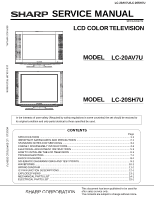
LC-20AV7U/LC-20SH7U
S37F3LC20AV7U
SERVICE MANUAL
MODEL
SERVICE MANUAL
LCD COLOR TELEVISION
MODELS
LC-20AV7U/LC-20SH7U
This document has been published to be used for
after sales service only.
The contents are subject to change without notice.
LC-20AV7U
Page
SPECIFICATIONS
...............................................................................................................................
1-1
IMPORTANT SAFEGUARDS AND PRECAUTIONS
...........................................................................
2-1
STANDARD NOTES FOR SERVICING
...............................................................................................
3-1
CABINET DISASSEMBLY INSTRUCTIONS
........................................................................................
4-1
ELECTRICAL ADJUSTMENT INSTRUCTIONS
..................................................................................
5-1
HOW TO INITIALIZE THE LCD TELEVISION
.....................................................................................
6-1
TROUBLESHOOTING
.........................................................................................................................
7-1
BLOCK DIAGRAMS
.............................................................................................................................
8-1
SCHEMATIC DIAGRAMS/ CBA'S AND TEST POINTS
.......................................................................
9-1
WAVEFORMS
....................................................................................................................................
10-1
WIRING DIAGRAM
............................................................................................................................
11-1
IC PIN FUNCTION DESCRIPTIONS
..................................................................................................
12-1
EXPLODED VIEWS
...........................................................................................................................
13-1
MECHANICAL PARTS LIST
...............................................................................................................
14-1
ELECTRICAL PARTS LIST
................................................................................................................
15-1
CONTENTS
LCD COLOR TELEVISION
In the interests of user-safety (Required by safety regulations in some countries) the set should be restored to
its original condition and only parts identical to those specified be used.
MODEL
LC-20SH7U