Sharp R1874 R-1870 , R- 1871 , R-1872 , R-1874 Installation Instructions
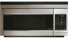
Sharp R1874 - 1.1 cu. Ft. Microwave Oven Manual
 |
UPC - 074000610910
View all Sharp R1874 manuals
Add to My Manuals
Save this manual to your list of manuals |
Sharp R1874 manual content summary:
- Sharp R1874 | R-1870 , R- 1871 , R-1872 , R-1874 Installation Instructions - Page 1
OVER THE RANGE MICROWAVE OVEN/HOOD SYSTEM INSTALLATION INSTRUCTIONS Please read all instructions thoroughly before installing the Microwave Oven/Hood System. Two people are recommended to install this product. If a new electrical outlet is required, its installation should be completed by a - Sharp R1874 | R-1870 , R- 1871 , R-1872 , R-1874 Installation Instructions - Page 2
Microwave Oven/Hood mounting location. Ground Receptacle NOTE: 1. If you have any questions about the grounding or electrical instructions, consult a qualified electrician or serviceperson. Opening for Power Cord 2. Neither Sharp parts INSTALLATION range-you may also use carton for protection 2 - Sharp R1874 | R-1870 , R- 1871 , R-1872 , R-1874 Installation Instructions - Page 3
PART CODE XTSS750P35000 LX-BZ0195WRE0 XBRS750P60000 XWHS750-16300 LBSHC0040MRE0 XOTS740P12000 FFTA-B004MRK0 Figure 5 7 PREPARATION OF THE OVEN Utilization of the carton may make installation , do not operate the oven and contact your dealer or SHARP AUTHORIZED SERVICER. 3. Place carton upside down - Sharp R1874 | R-1870 , R- 1871 , R-1872 , R-1874 Installation Instructions - Page 4
9. Figure 7 9 VENTILATION SYSTEM This Microwave Oven/Hood System is designed for adaptation to three types of hood ventilation systems. Select the type required for your installation. A. RECIRCULATING - Non-Vented, Ductless Operation The unit is shipped assembled for recirculating. NOTE: 1. The - Sharp R1874 | R-1870 , R- 1871 , R-1872 , R-1874 Installation Instructions - Page 5
Bracket. Make sure the fan blades are visible through the top openings in the oven before proceeding. 5. Attach the Fan Cover Bracket to unit with the 4 screws direction as the arrow. Use 1 Tapping Screw 4 X12 mm from the INSTALLATION HARDWARE and tighten into place. See Figure 17. (A) Rotate 180˚ - Sharp R1874 | R-1870 , R- 1871 , R-1872 , R-1874 Installation Instructions - Page 6
10 OVEN INSTALLATION THIS OVEN CANNOT BE PROPERLY INSTALLED WITHOUT REFERRING TO THE MOUNTING INSTRUCTIONS FOUND ON BOTH TEMPLATES. READ AND FOLLOW MOUNTING INFORMATION ON BOTH TOP CABINET AND WALL TEMPLATES. MOUNTING PLATE 1. Separate 4 Toggle Bolts 2, packed in the INSTALLATION HARDWARE, from the - Sharp R1874 | R-1870 , R- 1871 , R-1872 , R-1874 Installation Instructions - Page 7
hole as the oven is rotated upward. (In the case of a non-recessed bottom in the top cabinet, the hole for the cord may need to be enlarged.) Remove the carton portions. 6. Tighten the two unit mounting screws located in the grease filter openings. See Figure 23. 7. Install grease filters by fitting - Sharp R1874 | R-1870 , R- 1871 , R-1872 , R-1874 Installation Instructions - Page 8
from the oven. 3. Plug in the power cord. 4. Read the Operation Manual. 5. Keep the Installation Instructions for the local electrical inspector's use. ACCESSORIES Check with your dealer or order directly from the SHARP Accessories and Supplies Center. Call toll-free 1-800-BE SHARP (237-4277
-
 1
1 -
 2
2 -
 3
3 -
 4
4 -
 5
5 -
 6
6 -
 7
7 -
8
 |
 |

2
WALL CONSTRUCTION
This Microwave Oven/Hood should be mounted against and sup-
ported by a flat vertical wall. The wall must be flat for proper
installation. If the wall is not flat, use spacers to fill in the gaps.
Wall construction should be a minimum of 2" x 4" wood studding
and
3
/
8
" or more thick dry wall or plaster/lath. The mounting sur-
faces must be capable of supporting weight of 110 pounds—the
oven and contents—AND the weight of all items which would nor-
mally be stored in the top cabinet above the unit.
The unit should be attached to a minimum of one 2" x 4" wall stud.
To find the location of the studs, one of the following methods may
be used:
A. Use a stud finder, a magnetic device which locates the nails in
the stud.
B. Use a hammer to tap lightly across the mounting surface to find
a solid sound. This will indicate stud location.
The center of the stud can be located by probing the wall with a
small nail to find the edges of the stud and then placing a mark
halfway between the edges. The center of any adjacent studs will
normally be 16" or 24" to either side of this mark.
NOTE:
In the event that the unit will be unable to be supported by any stud, it will be necessary to use spe-
cial care in the placement of the toggle bolts and top cabinet screws. See Wall Template for details. The top
cabinet should be tested to ensure it is securely attached to the wall. Place extra weight up to 110 pounds
inside the top cabinet to test the support.
1
OVER THE RANGE MICROWAVE OVEN/HOOD SYSTEM
I
NSTALLATION INSTRUCTIONS
Please read all instructions thoroughly before installing the Microwave Oven/Hood System. Two people are
recommended to install this product.
If a new electrical outlet is required, its installation should be completed by a qualified electrician before the
Microwave Oven/Hood is installed. See 3 ELECTRICAL GROUNDING INSTRUCTIONS on page 2.
1
MOUNTING SPACE
This Microwave Oven/Hood requires a mounting space on a wall
as shown in Figure 1.
If the space between the wall cabinets is greater than 30-inches
(36-inches or 42-inches), a Filler Panel Kit may be used to fill the
gap between the Microwave Oven/Hood system and wall cabi-
nets. The Filler Panel Kit is sold as an optional accessory; each
kit contains two 3-inch panels. The Filler Panel Kit should be
installed before the Microwave Oven/Hood is installed.
For proper installation and servicing, a 2-inch space is necessary
between the top of the range backsplash and the bottom of the
Microwave Oven/Hood system.
30" or more
from cooking
surface
Backsplash
Figure 1
At least 2"
30"
12"
15.5"
2"x 4" Wood Studs
3/8" Dry Wall
or Plaster/lath
Figure 2
16" or 24"
66" or
more from
floor