Sony PCV-RX750 System Reference Manual
Sony PCV-RX750 - Vaio Desktop Computer Manual
 |
View all Sony PCV-RX750 manuals
Add to My Manuals
Save this manual to your list of manuals |
Sony PCV-RX750 manual content summary:
- Sony PCV-RX750 | System Reference Manual - Page 1
i - Sony PCV-RX750 | System Reference Manual - Page 2
providers may require a fee and credit card information. Financial services may require prior arrangements with participating financial institutions. Sony, VAIO, the VAIO logo, VAIO Digital Studio, VAIO Smart, MovieShaker, DVgate, Memory Stick, the Memory Stick logo, Giga Pocket, and i.LINK are - Sony PCV-RX750 | System Reference Manual - Page 3
STAR® Partner, Sony Corporation has determined effectively reduce energy consumption. It is an open system in which business proprietors can participate number and serial number are located on either the front or back panel of your Sony VAIO® computer. Record the model and serial number in the - Sony PCV-RX750 | System Reference Manual - Page 4
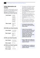
expose your desktop to rain or moisture. To avoid electrical shock, do not open the cabinet. Refer servicing to qualified personnel only. ❑ Never install modem or telephone wiring during a lightning storm. ❑ Never install telephone jacks in wet locations unless the jack is specifically designed for - Sony PCV-RX750 | System Reference Manual - Page 5
invisible laser radiation when open. Avoid direct exposure to jamais effectuer l'installation de fil modem ou téléphone durant un orage électrique. ❑ Ne jamais effectuer l'installation d'une de rechange, veuillez contacter votre centre de service Sony le plus près. ! Avertissement : L'utilisation - Sony PCV-RX750 | System Reference Manual - Page 6
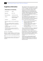
Manual Regulatory Information Declaration of Conformity Trade Name: SONY Model No.: PCV-7752 Responsible Party: Sony Electronics Inc. Address: 680 Kinderkamack Rd Oradell, NJ 07649 Telephone: 201-930-6972 This phone number is for FCC-related matters only. This device complies with Part - Sony PCV-RX750 | System Reference Manual - Page 7
with Part 68 of trouble is causing harm to the telephone network, the telephone company may request that you remove the equipment from the network until the problem is resolved. Repair of this equipment should be made only by a Sony Service Center or Sony authorized agent. For the Sony Service - Sony PCV-RX750 | System Reference Manual - Page 8
viii VAIO Digital Studio System Reference Manual Disposal of Lithium Battery You can return your unwanted lithium batteries to your nearest Sony Service Center or Factory Service Center. ✍ In some areas the disposal of lithium batteries in household or business trash may be prohibited. For the Sony - Sony PCV-RX750 | System Reference Manual - Page 9
the electrical ground connections of the power utility, telephone lines and internal metallic Conformity indicating that Industry Canada technical specifications were met. It does not lui-même; il doit avoir recours à un service d'inspection des installations électriques, ou à un électricien, selon - Sony PCV-RX750 | System Reference Manual - Page 10
x VAIO Digital Studio System Reference Manual confirmée par le numéro d'enregistrement, signifie que l'enregistrement s'est effectué conformément à une déclaration de conformité et indique que les specifications techniques d'Industrie Canada ont été respectées. Il n'implique pas qu'Industrie Canada - Sony PCV-RX750 | System Reference Manual - Page 11
1 - Identifying Components 1 Front View...2 Drives ...3 Buttons and Switches 4 Indicators 5 Connectors 6 Rear View ...7 Icon Labels 8 I/O Connectors 10 Expansion Slots 14 Chapter 2 - Configuring Your System 15 Accessing the BIOS Setup Utility 16 Changing Power Management Settings 17 xi - Sony PCV-RX750 | System Reference Manual - Page 12
Cover 37 Covering an Open I/O Slot 38 Installing an Internal Hard Disk Drive 39 To identify additional hard disk space 43 Removing the Power Supply 44 Replacing the Power Supply 45 Chapter 4 - System Board 47 Memory Module (DDR-DIMM) Slots 48 Power Supply and Aux Power Headers 49 CLR CMOS - Sony PCV-RX750 | System Reference Manual - Page 13
xiii Chapter 7 - Specifications 73 Processors 73 Chipset ...73 AGP Bus ...73 PCI Bus ...74 Memory Modules 74 Memory Configurations 74 L2 Cache ...74 Graphics ...74 Audio ...75 Communications 75 Giga Pocket I/O 75 I/O and Expansion Slots 76 Floppy Disk Drive and Controller 76 Hard Drives and - Sony PCV-RX750 | System Reference Manual - Page 14
xiv VAIO Digital Studio System Reference Manual - Sony PCV-RX750 | System Reference Manual - Page 15
Digital Studio™ computer. For details on the hardware confuguration of your system, see the online specifications sheet. To view this online information: 1 Click Start, then click Help and Support. 2 Click VAIO User Guide, then click the Welcome link. 3 Click the link in the text, "Click here to - Sony PCV-RX750 | System Reference Manual - Page 16
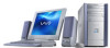
2 VAIO Digital Studio System Reference Manual Front View ✍ The computer shown in this section is equipped with Giga Pocket features. Your system's appearance may vary, depending on the configuration purchased. - Sony PCV-RX750 | System Reference Manual - Page 17
media slot Identifying Components 3 Optical disc drive #1 Optical disc drive #2 Drive Optical disc drive #1 Optical disc drive #2 Floppy disk drive Memory Stick® media slot Description See online specifications sheet for details. See online specifications sheet for details. 3.5-inch, 1.44 MB - Sony PCV-RX750 | System Reference Manual - Page 18
4 VAIO Digital Studio System Reference Manual Buttons and Switches Power on/off Optical disc eject Floppy disk eject Button or switch Optical disc eject button Floppy disk eject button Power on/off switch Description Automatically opens and closes the optical drive tray. Ejects a floppy disk. - Sony PCV-RX750 | System Reference Manual - Page 19
Indicators Identifying Components 5 Floppy disk drive access Hard disk drive access Optical disc drive access Power/Stand by Indicator Floppy disk drive access indicator Hard disk drive access indicator Optical drive access indicator Power/Stand by indicator Description On (green) indicates - Sony PCV-RX750 | System Reference Manual - Page 20
to an S-video cable (optional). Connects to an audio cable (supplied). Connects to a digital device that has a 4-pin i.LINK header. Connects to USB devices. * To connect to a 6-pin i.LINK device, use the i.LINK port on the back of the system. A 6-pin i.LINK connector can supply power from the - Sony PCV-RX750 | System Reference Manual - Page 21
port AV Out jacks AV In jacks Telephone jack KEYBOARD MOUSE USB NETWORK ACT LINK PRINTER i.LINK S400 HEADPHONES SERIAL LINE IN MIC 4 MONITOR 3 2 VIDEO VIDEO 1 OUTPUT INPUT S VIDEO S VIDEO /VIDEO /VIDEO VHF AUDIO AUDIO /UHF 1 LINE TELEPHONE AC Input port VHF/UHF port Line jack ✍ The computer - Sony PCV-RX750 | System Reference Manual - Page 22
Digital Studio System Reference Manual Icon Labels Icon KEYBOARD MOUSE USB NETWORK ACT LINK PRINTER i.LINK S400 HEADPHONES SERIAL LINE IN MIC 4 MONITOR 3 2 VIDEO VIDEO 1 OUTPUT INPUT S VIDEO S VIDEO /VIDEO /VIDEO VHF AUDIO AUDIO /UHF 1 LINE TELEPHONE Icon Label Area Icon Label Area Description - Sony PCV-RX750 | System Reference Manual - Page 23
Icon Description Printer/Parallel port i.LINK® (IEEE 1394) port Headphones Line In jack (audio) Microphone jack VGA Monitor port Line jack Telephone jack VHF/UHF port* Audio In jack* Audio Out jack* Video/S-video In jack* Video/S-video Out jack* * On models equipped with Giga Pocket features. - Sony PCV-RX750 | System Reference Manual - Page 24
I/O connectors. Keyboard and Mouse Ports The keyboard and mouse ports are physically identical and have the same pinout. They are standard 6-pin PS/2® compatible female ports. 2 3 1 4 6 5 USB Ports The USB ports are standard 4-pin USB ports. Two USB ports are located at the front, and - Sony PCV-RX750 | System Reference Manual - Page 25
port is a standard 9-pin DB-9 male port. 1 6 9 5 Printer/Parallel Port The printer/parallel port is a standard 25-pin DB-25 female port. 25 13 14 1 VGA Monitor Port The monitor port is a standard 15-pin female high-density VGA-type port located on the AGP plug-in card. 10 15 5 11 1 6 - Sony PCV-RX750 | System Reference Manual - Page 26
12 VAIO Digital Studio System Reference Manual Mic, Line In, and Headphones Jacks The microphone, line in, and headphones jacks are physically identical, but have different connections. They are standard 3.5 mm stereo mini-jacks. Headphones Line In Mic Connector Headphones Mic Line In - Sony PCV-RX750 | System Reference Manual - Page 27
. The 6-pin port supplies 10 V to 12 V and a maximum power of 6 watts. ✍ i.LINK is a trademark of Sony used only to designate hard disk drive, confirm their operating system compatibility and required operating conditions. The 4-pin i.LINK port at the bottom of the front panel does not supply power - Sony PCV-RX750 | System Reference Manual - Page 28
VAIO Digital Studio System Reference Manual Expansion Slots There are five expansion slots (see "System Board" on page 47). Expansion (slot No.1) is occupied by the fax/modem card have a Giga Pocket™ card installed. There is one AGP (slot No.5), which is occupied by an AGP card. Slot No. 5 Slot panel. - Sony PCV-RX750 | System Reference Manual - Page 29
Chapter 2 Configuring Your System This chapter contains information on configuring your system. ❑ Making changes to the BIOS settings. ❑ Making changes to the display's power management settings. 15 - Sony PCV-RX750 | System Reference Manual - Page 30
16 VAIO Digital Studio System Reference Manual Accessing the BIOS Setup Utility Access the BIOS Setup Utility to make changes to the BIOS settings (see "CMOS Setup Options" on page 53 for information on BIOS settings). ! Before rebooting the system, save and close all open files, and exit open - Sony PCV-RX750 | System Reference Manual - Page 31
for a specified period of time. 1 From the Start menu, point to Settings, click Control Panel, then click Display. The Power Options Properties dialog box opens, with the Power Schemes tab displayed. 2 Select the power scheme that is most appropriate for the way you use your computer. To change - Sony PCV-RX750 | System Reference Manual - Page 32
18 VAIO Digital Studio System Reference Manual The Turn off monitor option enables you to specify the period of inactivity (in minutes) that you want to elapse before your monitor turns off when your computer is running on AC power. The display reactivates when you move the mouse or press a key. The - Sony PCV-RX750 | System Reference Manual - Page 33
4 Click the Advanced tab. Configuring Your System 19 5 Select the desired settings. - Sony PCV-RX750 | System Reference Manual - Page 34
20 VAIO Digital Studio System Reference Manual 6 Click the Hibernate tab. 7 Select the settings most appropriate for your system. - Sony PCV-RX750 | System Reference Manual - Page 35
an Uninterruptible Power Supply (UPS) device for your system. ✍ A UPS device is an optional accessory not supplied with your system. 9 Select the settings most appropriate for your system and click OK. For more information about configuring a UPS device, refer to your Microsoft® Windows® XP - Sony PCV-RX750 | System Reference Manual - Page 36
22 VAIO Digital Studio System Reference Manual - Sony PCV-RX750 | System Reference Manual - Page 37
Components This chapter describes upgrade and maintenance procedures. ! Before opening the system unit, save and close all open files, exit all open applications, turn off the power to all attached peripheral devices, shut down the computer, and unplug the power cord. ✍ System configuration may - Sony PCV-RX750 | System Reference Manual - Page 38
24 VAIO Digital Studio System Reference Manual Removing the Side Panel You must remove the side panel to access the system board, add-in cards, power supply, battery, memory, and internal drives. 1 Locate the tab on the upper right side of the rear panel, and pull it back until the side panel - Sony PCV-RX750 | System Reference Manual - Page 39
Upgrading and Maintaining Components 25 Replacing the Side Panel 1 Align the tabs on the side panel to the chassis frame. 2 Press the side panel firmly against the unit until it snaps into place. - Sony PCV-RX750 | System Reference Manual - Page 40
26 VAIO Digital Studio System Reference Manual Removing a PCI Add-in Card ! Before opening the system unit, save and close all open files, exit all open applications, turn off the power to all attached peripheral devices, shut down the computer, and unplug the power cord. 1 Remove the side panel ( - Sony PCV-RX750 | System Reference Manual - Page 41
power supply) before handling an add-in card to discharge any static electricity in your body. 5 If you do not replace the card or install another add-in card, install a slot cover over the vacant slot at the rear of the chassis (see "Covering an Open I/O Slot" on page 38). 6 Replace the side panel - Sony PCV-RX750 | System Reference Manual - Page 42
28 VAIO Digital Studio System Reference Manual Installing a PCI Add-In Card ! Before opening the system unit, save and close all open files, exit all open applications, turn off the power to all attached peripheral devices, shut down the computer, and unplug the power cord. 1 Remove the side panel ( - Sony PCV-RX750 | System Reference Manual - Page 43
Upgrading and Maintaining Components 29 6 Attach any necessary cables to the card (see the instructions that came with the add-in card). 7 Replace the side panel (see "Replacing the Side Panel" on page 25). 8 Turn on the computer and follow any instructions that came with the add-in card. - Sony PCV-RX750 | System Reference Manual - Page 44
30 VAIO Digital Studio System Reference Manual Replacing the Lithium Battery ! Before opening the system unit, save and close all open files, exit all open applications, turn off the power to all attached peripheral devices, shut down the computer, and unplug the power cord. You may need to replace - Sony PCV-RX750 | System Reference Manual - Page 45
a type of battery other than a CR2032 may present a risk of fire or explosion. 12 Replace any add-in cards that were removed. 13 Reconnect any cables that were disconnected. 14 Replace the side panel (see "Replacing the Side Panel" on page 25). 15 Reconnect the power cord and turn on the computer. - Sony PCV-RX750 | System Reference Manual - Page 46
32 VAIO Digital Studio System Reference Manual 16 If the error message "Error: Check date and time settings." appears during the reboot sequence, press F2 during the reboot process to access the BIOS Setup Utility. If no error message displays, the computer's BIOS settings were retained during the - Sony PCV-RX750 | System Reference Manual - Page 47
exit all open applications, turn off the power to all attached peripheral devices, shut down the computer, and unplug the power cord. 1 Remove the side panel (see "Removing the Side Panel" on page 24). 2 Remove the power supply (see "Removing the Power Supply" on page 44). 3 Locate the memory module - Sony PCV-RX750 | System Reference Manual - Page 48
34 VAIO Digital Studio System Reference Manual Installing a Memory Module ! Before opening the system unit, save and close all open files, exit all open applications, turn off the power to all attached peripheral devices, shut down the computer, and unplug the power cord. 1 Choose the size of the - Sony PCV-RX750 | System Reference Manual - Page 49
any components or contacts on the card. Static electricity in your body may damage sensitive components on the card. As a precaution, touch any exposed metal part on the metal chassis (preferably the metal part on the power supply) before handling an add-in card to discharge any static electricity - Sony PCV-RX750 | System Reference Manual - Page 50
slot on the AGP card. 13 Replace the power supply (see "Replacing the Power Supply" on page 45). 14 Replace the side panel (see "Replacing the Side Panel" on page 25). 15 Reconnect the power cord and turn on the computer. Your computer automatically recognizes the extra memory and configures itself - Sony PCV-RX750 | System Reference Manual - Page 51
when you install an add-in card that occupies a previously empty slot. ! Before opening the system unit, save and close all open files, exit all open applications, turn off the power to all attached peripheral devices, shut down the computer, and unplug the power cord. 1 Remove the side panel (see - Sony PCV-RX750 | System Reference Manual - Page 52
38 VAIO Digital Studio System Reference Manual Covering an Open I/O Slot ! Before opening the system unit, save and close all open files, exit all open applications, turn off the power to all attached peripheral devices, shut down the computer, and unplug the power cord. Slot covers prevent air from - Sony PCV-RX750 | System Reference Manual - Page 53
-66 or ATA-100 hard disk drives. Sony recommends an ATA-100 hard disk drive to take full advantage of the system's features. The drive you install must not require front panel access. The hard disk drive access light blinks when either internal drive is active. ! Before opening the system unit, save - Sony PCV-RX750 | System Reference Manual - Page 54
40 VAIO Digital Studio System Reference Manual 3 Disconnect the drive connector (A). A B C Drive connector Power supply connector Tab Disk drive holder 4 Disconnect the power connector (B). 5 Pull out on the tab (C) that secures the drive holder to the chassis. - Sony PCV-RX750 | System Reference Manual - Page 55
Upgrading and Maintaining Components 41 6 Slide the drive holder up and out. 7 Slide the new drive into the bottom part of the drive holder and align the holes on each side of the drive holder. 8 Secure the drive to the drive holder using screws in each of the two holes on each side of the drive - Sony PCV-RX750 | System Reference Manual - Page 56
42 VAIO Digital Studio System Reference Manual 10 Push in on the tab (A) to securely latch the holder to the chassis. C E B D A Drive connectors Power connectors Tab Disk drive holder 11 Connect the inner drive cable connector (B) to the first drive. 12 Connect the outer drive cable connector - Sony PCV-RX750 | System Reference Manual - Page 57
Upgrading and Maintaining Components 43 To identify additional hard disk space When you initialize the new hard disk drive, it must be configured as an extended partition in Windows NT file system (NTFS) format. 1 Log on in Windows® as Administrator. 2 Click Start in the Windows taskbar and right- - Sony PCV-RX750 | System Reference Manual - Page 58
44 VAIO Digital Studio System Reference Manual Removing the Power Supply You remove the power supply when you insert a memory module (see "Installing a Memory Module" on page 34). ! Before opening the system unit, save and close all open files, exit all open applications, turn off the power to all - Sony PCV-RX750 | System Reference Manual - Page 59
Upgrading and Maintaining Components 45 Replacing the Power Supply 1 Rotate the power supply down and slide it down along the rails on each side of the chassis opening. 2 Replace the screw that secures the power supply to the rear of the chassis. - Sony PCV-RX750 | System Reference Manual - Page 60
46 VAIO Digital Studio System Reference Manual - Sony PCV-RX750 | System Reference Manual - Page 61
CPU Fan Memory Stick Connector Processor Memory USB3, USB4 Ethernet Printer, i.LINK 1394 Header 3 Serial Port, Mic In, Line In Line Out CD-In (not used) Aux-In (not used) Slot No. 1 (CNR) Slot No. 2 (PCI) Slot No. 3 (PCI) Slot No. 4 (PCI) Aux Power Supply Power Supply Fan Power Supply Diskette - Sony PCV-RX750 | System Reference Manual - Page 62
DDR-DIMM1 DDR-DIMM2 DDR-DIMM3 48 VAIO Digital Studio System Reference Manual Memory Module (DDR-DIMM) Slots Memory module (DDR-DIMM) 1 Indicates pin 1 Align pin 1 of the Dual Inline Memory Module (DDR-DIMM) to the small triangle located on the memory module slot of the system board. - Sony PCV-RX750 | System Reference Manual - Page 63
Board 49 Power Supply and Aux Power Headers The power supply header on the system board connects to the power supply header labelled P1. 2 4 1 3 10 20 1 11 Power Supply header Pin Signal Name 1 +3.3 V 2 +3.3 V 3 Ground 4 +5 V 5 Ground 6 +5 V 7 Ground 8 PWRGD (Power Good - Sony PCV-RX750 | System Reference Manual - Page 64
50 VAIO Digital Studio System Reference Manual Power Supply header (Continued) Pin Signal Name 17 Ground 18 No Connection 19 +5 V 20 +5 V Aux Power header Pin Signal Name 1 Ground 2 Ground 3 +12 V 4 +12 V - Sony PCV-RX750 | System Reference Manual - Page 65
Jumper The CLR CMOS Jumper clears the BIOS password setting. CLR CMOS 1 2 3 CLR CMOS Jumper settings Jumper Plug Position 2-3 1-2 Function Normal Clear CMOS Password ✍ The configuration jumpers should never need changing unless otherwise directed by a technical support or service technician. - Sony PCV-RX750 | System Reference Manual - Page 66
52 VAIO Digital Studio System Reference Manual - Sony PCV-RX750 | System Reference Manual - Page 67
BIOS Setup Utility (see "Accessing the BIOS Setup Utility" on page 16). The Award BIOS setup has five menu items on the menu bar. These are: ❑ Main ❑ Advanced ❑ Power are shown without brackets directly below the default option in this guide. The available options are listed in the order they occur - Sony PCV-RX750 | System Reference Manual - Page 68
54 VAIO Digital Studio System Reference Manual Press F10 to save the changes and exit, or press Esc to discard the changes. Follow the on-screen prompts for other choices. The bottom of the screen presents a summary of the keys to use for navigation and control. - Sony PCV-RX750 | System Reference Manual - Page 69
56) Secondary Master (see "IDE Sub-Menus" on page 56) Secondary Slave (see "IDE Sub-Menus" on page 56) Supervisor Password [Disabled] User Password [Disabled] Installed Memory See online specifications sheet for details. BIOS Revision/Version 1003 (depends on model) - Sony PCV-RX750 | System Reference Manual - Page 70
56 VAIO Digital Studio System Reference Manual IDE Sub-Menus Type Translation Method* Cylinders† Heads† Sectors‡ CHS Capacity* Maximum LBA Capacity* [Auto] User Type HDD CD-ROM LS-120 ZIP-100 MO Other ATAPI None [LBA] Large Normal Match Partition Table Manual [1024] [255] [63] 8422 MB 40992 MB ( - Sony PCV-RX750 | System Reference Manual - Page 71
CMOS Setup Options 57 Advanced Screen CPU Internal Frequency [1500MHz]* I/O Device Configuration (see "I/O Device Configuration Sub-Menu" on page 58) PCI Configuration (see "PCI Configuration Sub-Menu" on page 58) * CPU Internal Frequency may vary, depending on the model purchased. - Sony PCV-RX750 | System Reference Manual - Page 72
58 VAIO Digital Studio System Reference Manual I/O Device Configuration Sub-Menu Onboard AC97 Audio Controller [Enabled] Disabled Onboard AC97 Modem Controller [Auto] Disabled Onboard 1394 Controller [Enabled] Disabled Onboard Lan Controller [Enabled] Disabled Onboard Memory Stick Controller - Sony PCV-RX750 | System Reference Manual - Page 73
Control AC PWR Loss Restart PWR Up On Modem Act Wake On LAN Hardware Monitor MB Temperature CPU Temperature CPU Fan Speed Power Fan Speed VCORE Voltage +3.3V Voltage +5V Voltage CMOS Setup Options 59 [Disabled] Enabled [Disabled] Enabled [Disabled] Enabled [(displays actual temperature)] Ignore - Sony PCV-RX750 | System Reference Manual - Page 74
60 VAIO Digital Studio System Reference Manual Boot Screen 1. ATAPI CD-ROM 2. Removable Device 3. IDE Hard Drive 4. Other Boot Device Silent Boot [(displays installed drive)] Disabled [Legacy Floppy] LS120 ATAPI MO Disabled [(displays installed drive)] Disabled [Disabled] INT18 Device (Network) - Sony PCV-RX750 | System Reference Manual - Page 75
Exit Screen Exit Saving Changes Exit Discarding Changes Load Setup Defaults Discard Changes Save Changes CMOS Setup Options 61 - Sony PCV-RX750 | System Reference Manual - Page 76
62 VAIO Digital Studio System Reference Manual - Sony PCV-RX750 | System Reference Manual - Page 77
: ❑ User and Supervisor password ❑ Beep code error messages ❑ PCI configuration status and error messages ❑ DMA channel assignments ❑ System I/O address map ❑ Memory map ❑ IRQ settings ✍ Models equipped with Giga Pocket features may require increased system resources due to additional hardware. 63 - Sony PCV-RX750 | System Reference Manual - Page 78
64 VAIO Digital Studio System Reference Manual User and Supervisor Passwords The system allows you to specify up to two passwords (a User password and a Supervisor password) in the CMOS Setup Utility. The - Sony PCV-RX750 | System Reference Manual - Page 79
Messages During a normal bootup, a single short beep signifies that the system is OK. Other beep patterns signify errors. The number of beeps indicates the specific error that occurred. If a system error occurs, the Sony Online Support technicians require the number of beeps your system produces. - Sony PCV-RX750 | System Reference Manual - Page 80
VAIO Digital Studio System Reference Manual Full PCI I/O Port Conflict PCI IRQ Conflict PCI Memory Conflict Primary Boot Device Not Found Primary IDE Controller conflict. The designated primary boot device (hard disk drive, floppy disk drive, CD-ROM drive, or network drive) could not be found. The - Sony PCV-RX750 | System Reference Manual - Page 81
Miscellaneous Technical Information 67 Message Static Device Resource Conflict System Board Device Resource Conflict Meaning A non-Plug and Play ISA card has requested a resource that is already in use. A non-Plug and-Play ISA card has requested a resource that is already in use. - Sony PCV-RX750 | System Reference Manual - Page 82
68 VAIO Digital Studio System Reference Manual DMA Channel Assignments This shows the factory default values. The Windows® operating system reassigns resources to best meet the needs of a particular configuration. DMA Channel Channel 4 Channel 2 Default Assignment Direct memory access controller - Sony PCV-RX750 | System Reference Manual - Page 83
resources Motherboard resources Motherboard resources Motherboard resources Motherboard resources Motherboard resources Motherboard resources Motherboard resources Motherboard resources Motherboard resources Programmable interrupt controller Programmable interrupt controller Direct memory access - Sony PCV-RX750 | System Reference Manual - Page 84
resources Motherboard resources Sony Memory Stick controller(WB) SiS PCI IDE Controller Primary IDE Channel Primary IDE Channel Secondary IDE Channel Secondary IDE Channel Lucent Technologies Soft Modem AMR Lucent Technologies Soft Modem AMR SiS 7012 Audio Driver SiS 7012 Audio Driver Realtek - Sony PCV-RX750 | System Reference Manual - Page 85
Miscellaneous Technical Information 71 Memory Map Address range 0x0000-0x9FFFF 0xF0000-0xFFFFF 0x100000- SiS 650_740 SiS Accelerated Graphics Port Motherboard resources Motherboard resources SiS 7001 PCI to USB Open Host Controller SiS 7001 PCI to USB Open Host Controller Realtek RTL8139/810X - Sony PCV-RX750 | System Reference Manual - Page 86
72 VAIO Digital Studio System Reference Manual IRQ Settings IRQ Description 0 System timer 1 Standard 101/102-Key or Microsoft® Natural PS/2® Keyboard 4 Communications Port (COM1) 6 Standard floppy disk controller 8 System CMOS/real time clock 11 Sony Memory Stick controller(WB) 12 - Sony PCV-RX750 | System Reference Manual - Page 87
Chapter 7 Specifications This chapter describes the technical specifications for your VAIO Digital Studio™ computer. Processors See online specifications sheet for details. Chipset SiS 650 chipset AGP Bus AGP interface specification, version 2.0 (supports 2x/4x) 1 AGP slot 73 - Sony PCV-RX750 | System Reference Manual - Page 88
74 VAIO Digital Studio System Reference Manual PCI Bus PCI Level 2.2, 33 MHz zero wait state 3 PCI slots, 2 open. Not all PCI slots available. (See online specifications sheet for details.) Memory Modules Installed memory Maximum memory Voltage Pins Memory type See online specifications sheet - Sony PCV-RX750 | System Reference Manual - Page 89
Specifications 75 Audio Sound chip Wave synthesis Sound effects Audio sampling rate Rear panel connectors SiS 7012 Software synthesis DirectX® software Up to 48 kHz at 16-bits Mic (for microphone) Line In (from stereo audio source) Headphones (for stereo - Sony PCV-RX750 | System Reference Manual - Page 90
(front panel) USB3 and USB4 (rear panel) (See online specifications sheet for details.) Not all PCI slots are available for expansion. See online specifications sheet for details. One slot for a CNR modem. Primary and secondary (each supports two IDE drives) * Universal Serial Port (USB) technology - Sony PCV-RX750 | System Reference Manual - Page 91
Make and model ROM Passwords Power management Advanced features Plug and Play devices Special features Specifications 77 Award-based 2 Mb Flash-ROM User and supervisor passwords supported APM 1.2 ACPI-1.0 compliant hardware for use with APM and PNP BIOS APIs Supported with steerable DMA channels - Sony PCV-RX750 | System Reference Manual - Page 92
78 VAIO Digital Studio System Reference Manual - Sony PCV-RX750 | System Reference Manual - Page 93
for 76 expansion slots - See Also slots F fax/modem - See modem card floppy disk drive specifications 76 front view 2 buttons and switches 4 connectors 5, 6 indicators 5 G Giga Pocket specifications 75 graphics controller - See graphics graphics specifications 74 H hard drive specifications 76 79 - Sony PCV-RX750 | System Reference Manual - Page 94
64 PCI add-in card installing 28 removing 26 PCI bus specifications 74 power connector 49 power management, configuring 17 processor specifications 73, 74 R RAM - See system memory rear view 7 I/O connectors 10 icons 8 removing memory module 33 PCI add-in card 26 side panel 24 slot cover 37 - Sony PCV-RX750 | System Reference Manual - Page 95
Index 81 specifications AGP bus 73 audio 75 BIOS 77 chipset 73 communications 75 floppy disk drive and controller 76 Giga Pocket 75 graphics 74 hard drives and controllers 76 I/O and expansion slots 76 L2 cache 74 memory configurations 74 memory module 74 optical drives 76 PCI bus 74 processor 73, - Sony PCV-RX750 | System Reference Manual - Page 96
82 VAIO Digital Studio System Reference Manual
-
 1
1 -
 2
2 -
 3
3 -
 4
4 -
 5
5 -
 6
6 -
 7
7 -
8
-
9
-
10
-
11
-
12
-
13
-
14
-
15
-
16
-
17
-
18
-
19
-
20
-
21
-
22
-
23
-
24
-
25
-
26
-
27
-
28
-
29
-
30
-
31
-
32
-
33
-
34
-
35
-
36
-
37
-
38
-
39
-
40
-
41
-
42
-
43
-
44
-
45
-
46
-
47
-
48
-
49
-
50
-
51
-
52
-
53
-
54
-
55
-
56
-
57
-
58
-
59
-
60
-
61
-
62
-
63
-
64
-
65
-
66
-
67
-
68
-
69
-
70
-
71
-
72
-
73
-
74
-
75
-
76
-
77
-
78
-
79
-
80
-
81
-
82
-
83
-
84
-
85
-
86
-
87
-
88
-
89
-
90
-
91
-
92
-
93
-
94
-
95
-
96
 |
 |