Sony PVM-2030/BS Operating Instructions - Page 17
Sony PVM-2030/BS Manual
 |
View all Sony PVM-2030/BS manuals
Add to My Manuals
Save this manual to your list of manuals |
Page 17 highlights
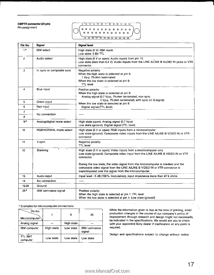
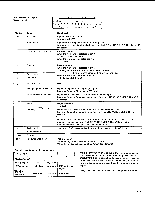
CMPTR connector (25-pin) Pin assignment 1 2 3 4 5 6 7 8 9 10 11 12 13 O O O O O O O O O O O O O O O O O OOO OOO O O O O 14 15 16 17 18 19 20 21 22 23 24 25 Pin No. 1* 2 3 4 5 6 7 8 9* 10 11 12 Signal IBM select Audio select H. sync or composite sync Blue input Green input Red input No connection Analog/digital mode select RGB/NORMAL mode select V-sync Blanking . . Signal level High state (5 V): IBM mode Low state: 3 Bit TTL High state (5 V or open): Audio inputs from pin 13. _ Low state (less than 0.4 V): Audio inputs from the LINE A/LINE B AUDIO IN jacks or VTR connector Negative polarity When the high state is selected at pin 9: 1 Vp-p, 75-ohm terminated When the low state is selected at pin 9: TTL level Positive polarity When the high state is selected at pin 9: Analog signal (0.7 Vp-p, 75-ohm terminated, non sync 1 Vp-p, 75-ohm terminated, with sync on G-signal) When the low state is selected at pin 9: Digital signal (TTL level) - High state (open): Analog signal (0.7 Vp-p) Low state (ground): Digital signal (TTL level) High state (5 V or open): RGB inputs from a microcomputer Low state (ground): Composite video inputs from the LINE A/LINE B VIDEO IN or VTR connector Negative polarity TTL level High state (5 V or open): Video inputs from a microcomputer only Low state (ground): Composite video input from the LINE A/LINE B VIDEO IN or VTR connector 13 14 15-24 25* Audio input No connection Ground IBM luminance signal During the low state, the video signal from the microcomputer is blanked and the composite video signal from the LINE A/LINE B VIDEO IN or VTR connector is superimposed over the signal from the microcomputer. Input level -5 dB (100% modulation), input impedance more than 47 k ohms - Positive polarity When the high state is selected at pin 1: TTL level When the low state is selected at pin 1: Low state (ground) * Examples for microcomputer connections Pin No. 1 9 Microcomputer Analog signal - High state IBM computer High state Low state TTL 3BIT computer Low state Low state 25 - IBM luminance signal Low state While the information given is true at the time of printing, small production changes in the course of our company's policy of improvement through research and design might not necessarily be indicated in the specifications. We would ask you to check with your appointed Sony dealer if clarification on any point is required. Design and specifications subject to change without notice. 17
-
 1
1 -
2
-
3
-
4
-
5
-
6
-
7
-
8
-
9
-
10
-
11
-
 12
12 -
 13
13 -
 14
14 -
 15
15 -
 16
16 -
 17
17 -
 18
18
 |
 |