Stihl MS 181 C-BE Parts Diagram
Stihl MS 181 C-BE Manual
 |
View all Stihl MS 181 C-BE manuals
Add to My Manuals
Save this manual to your list of manuals |
Stihl MS 181 C-BE manual content summary:
- Stihl MS 181 C-BE | Parts Diagram - Page 1
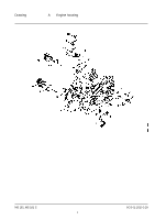
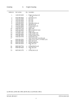
Drawing A Engine housing MS 181, MS 181 C 1 SCS 01-2010 3.29 - Stihl MS 181 C-BE | Parts Diagram - Page 2
12 1139 358 7704 13 1123 664 2400 14 1123 664 2402 15 1139 442 1600 16 1139 353 2700 17 0000 930 2803 18 Filler cap (1,3) 21 1 O-ring 25x3.5 (1,3) 1 Filler cap (1,3) 23 1 O-ring 23x3 (1,3) (1) MS 181, (2) MS 181 C-BE, (3) MS 181-Z, (4) MS 181 C-BE Z MS 181, MS 181 C 2 SCS 01-2010 3.29 - Stihl MS 181 C-BE | Parts Diagram - Page 3
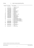
Drawing B Engine housing ErgoStart/Easy2Start MS 181, MS 181 C 3 SCS 01-2010 3.29 - Stihl MS 181 C-BE | Parts Diagram - Page 4
12 1139 358 7704 13 1123 664 2400 14 1123 664 2402 15 1139 442 1600 16 1139 353 2701 17 4130 350 6200 18 Filler cap (2,4) 24 1 O-ring 25x3.5 (2,4) 1 Filler cap (2,4) 26 1 O-ring 23x3 (2,4) (1) MS 181, (2) MS 181 C-BE, (3) MS 181-Z, (4) MS 181 C-BE Z MS 181, MS 181 C 4 SCS 01-2010 3.29 - Stihl MS 181 C-BE | Parts Diagram - Page 5
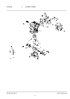
Drawing C Cylinder, Muffler MS 181, MS 181 C 5 SCS 01-2010 3.29 - Stihl MS 181 C-BE | Parts Diagram - Page 6
021 2503 13 0000 400 7011 14 1139 140 0602 15 1139 140 0601 16 1139 141 9000 17 1139 141 16 1 Screen (3,4) USA, AUS, CDN 1 Cooling plate 2 Pan head self-tapping screw IS-D5x18 2 Plug 1 Tube of sealant Dirko HT red (1) MS 181, (2) MS 181 C-BE, (3) MS 181-Z, (4) MS 181 C-BE Z MS 181, MS 181 - Stihl MS 181 C-BE | Parts Diagram - Page 7
Drawing D Rewind starter MS 181, MS 181 C 7 SCS 01-2010 3.29 - Stihl MS 181 C-BE | Parts Diagram - Page 8
9074 477 4139 14 0000 190 3402 15 0000 195 8200 16 0000 195 7001 16 1 Starter rope Ø 3x800 mm (B) (1,3) 1 Cap (B) (1,3) 1 Cover plate kit (B) (1,3) 17, 18 1 Cover plate (B) (1,3) 2 Self-tapping screw 3.9x13 (B) (1,3) (1) MS 181, (2) MS 181 C-BE, (3) MS 181-Z, (4) MS 181 C-BE Z MS 181, MS 181 - Stihl MS 181 C-BE | Parts Diagram - Page 9
Drawing E Rewind starter ErgoStart/Easy2Start MS 181, MS 181 C 9 SCS 01-2010 3.29 - Stihl MS 181 C-BE | Parts Diagram - Page 10
12 1139 195 2000 13 0000 958 0806 14 9455 621 0570 15 1139 084 7800 16 1139 967 1502 17 9074 477 4135 18 MS 181 C (2,4) 3 Pan head self-tapping screw IS-P5x20 (2,4) 1 Pan head self-tapping screw IS-P5x25 (2,4) (1) MS 181, (2) MS 181 C-BE, (3) MS 181-Z, (4) MS 181 C-BE Z MS 181, MS 181 - Stihl MS 181 C-BE | Parts Diagram - Page 11
Drawing F Ignition system MS 181, MS 181 C 11 SCS 01-2010 3.29 - Stihl MS 181 C-BE | Parts Diagram - Page 12
9075 478 3018 11 9291 021 0100 12 1139 405 8000 13 1139 448 1200 14 1139 440 3000 Qty Description 1 Flywheel (1,3) (25.2005) 1 Collar nut M8x1 1 Insulator 1 Lead retainer 1 Wiring harness (1) MS 181, (2) MS 181 C-BE, (3) MS 181-Z, (4) MS 181 C-BE Z MS 181, MS 181 C 12 SCS 01-2010 3.29 - Stihl MS 181 C-BE | Parts Diagram - Page 13
Drawing G Hand guard, Chain brake MS 181, MS 181 C 13 SCS 01-2010 3.29 - Stihl MS 181 C-BE | Parts Diagram - Page 14
14 1121 162 1001 15 1123 640 7102 16 Chain sprocket cover (1,3) 1 Hexagon nut M8 (1,3) 1 Instruction label (3,4) USA 1 Chain catcher (20.2007) 32, 33 1 Countersunk screw M6x14 (20.2007) 1 Lock nut M6 (20.2007) (1) MS 181, (2) MS 181 C-BE, (3) MS 181-Z, (4) MS 181 C-BE Z MS 181, MS 181 C 14 - Stihl MS 181 C-BE | Parts Diagram - Page 15
Drawing H Quick chain tensioner MS 181, MS 181 C 15 SCS 01-2010 3.29 - Stihl MS 181 C-BE | Parts Diagram - Page 16
021 2800 13 1123 664 0501 14 9075 478 4115 15 0812 370 1000 Qty Description 1 Quick tensioner parts (B) 1 - 15 1 Chain sprocket cover (2,4) 2 - 4 IS-D5x16 (2,4) 1 Screwdriver T27x120x70 (B) (1) MS 181, (2) MS 181 C-BE, (3) MS 181-Z, (4) MS 181 C-BE Z MS 181, MS 181 C 16 SCS 01-2010 3.29 - Stihl MS 181 C-BE | Parts Diagram - Page 17
Drawing J Air filter, Manifold MS 181, MS 181 C 17 SCS 01-2010 3.29 - Stihl MS 181 C-BE | Parts Diagram - Page 18
0605 10 1139 120 0606 11 1139 120 0900 12 1139 141 1801 13 1139 140 2500 14 9075 478 3012 Qty Description 1 Air filter, fleece 1 Air filter (B) 1 Filter base self-tapping screw IS-D4x12 (1) MS 181, (2) MS 181 C-BE, (3) MS 181-Z, (4) MS 181 C-BE Z MS 181, MS 181 C 18 SCS 01-2010 3.29 - Stihl MS 181 C-BE | Parts Diagram - Page 19
Drawing K Carburetor C1Q-S121B MS 181, MS 181 C 19 SCS 01-2010 3.29 - Stihl MS 181 C-BE | Parts Diagram - Page 20
7300 12 1139 122 3200 13 4282 122 9000 14 1139 126 0300 15 1125 122 7402 16 1120 122 6601 17 1139 120 9700 18 1139 head screw (1,3) 1 Choke shaft with lever (1,3) 1 Torsion spring (1,3) (1) MS 181, (2) MS 181 C-BE, (3) MS 181-Z, (4) MS 181 C-BE Z MS 181, MS 181 C 20 SCS 01-2010 3.29 - Stihl MS 181 C-BE | Parts Diagram - Page 21
Drawing K Carburetor C1Q-S121B MS 181, MS 181 C 21 SCS 01-2010 3.29 - Stihl MS 181 C-BE | Parts Diagram - Page 22
2 E-clip (1,3) 1 Throttle lever (1,3) 1 Torsion spring (1,3) 1 Throttle lever (1,3) 1 Flat head screw M3x3.5 (1,3) 1 Idle speed adjustment screw (1,3) 1 Set of carburetor parts (1,3) 8, 9, 26, 27 (1) MS 181, (2) MS 181 C-BE, (3) MS 181-Z, (4) MS 181 C-BE Z MS 181, MS 181 C 20 SCS 01-2010 3.29 - Stihl MS 181 C-BE | Parts Diagram - Page 23
Drawing L Carburetor C1Q-S122B MS 181, MS 181 C 23 SCS 01-2010 3.29 - Stihl MS 181 C-BE | Parts Diagram - Page 24
7300 12 1139 122 3200 13 4282 122 9000 14 1139 126 0300 15 1125 122 7402 16 1120 122 6601 17 1139 120 9700 18 1139 head screw (2,4) 1 Choke shaft with lever (2,4) 1 Torsion spring (2,4) (1) MS 181, (2) MS 181 C-BE, (3) MS 181-Z, (4) MS 181 C-BE Z MS 181, MS 181 C 24 SCS 01-2010 3.29 - Stihl MS 181 C-BE | Parts Diagram - Page 25
Drawing L Carburetor C1Q-S122B MS 181, MS 181 C 25 SCS 01-2010 3.29 - Stihl MS 181 C-BE | Parts Diagram - Page 26
2 E-clip (2,4) 1 Throttle lever (2,4) 1 Torsion spring (2,4) 1 Throttle lever (2,4) 1 Flat head screw M3x3.5 (2,4) 1 Idle speed adjustment screw (2,4) 1 Set of carburetor parts (2,4) 8, 9, 26, 27 (1) MS 181, (2) MS 181 C-BE, (3) MS 181-Z, (4) MS 181 C-BE Z MS 181, MS 181 C 24 SCS 01-2010 3.29 - Stihl MS 181 C-BE | Parts Diagram - Page 27
Drawing M Handle frame, Shroud MS 181, MS 181 C 27 SCS 01-2010 3.29 - Stihl MS 181 C-BE | Parts Diagram - Page 28
1139 792 2900 14 1139 182 1000 15 1117 182 4500 16 1139 182 0800 frame (1,3) 1 Handle frame (2,4) 1 Warning pictogram MS 1 Instruction label (3,4) USA 1 Spring 1 Retainer 1 Bearing USA, CDN (1) MS 181, (2) MS 181 C-BE, (3) MS 181-Z, (4) MS 181 C-BE Z MS 181, MS 181 C 28 SCS 01-2010 3. - Stihl MS 181 C-BE | Parts Diagram - Page 29
Drawing N Tools, Extras MS 181, MS 181 C 29 SCS 01-2010 3.29 - Stihl MS 181 C-BE | Parts Diagram - Page 30
0000 792 9152 4 0812 370 1000 5 0000 891 0801 6 1110 893 4000 Qty Description 1 Combination wrench 1 Screwdriver 1 Chain scabbard 1 Screwdriver T27x120x70 (B) 1 Tool roll (B) 1 Filing gauge (B) (1) MS 181, (2) MS 181 C-BE, (3) MS 181-Z, (4) MS 181 C-BE Z MS 181, MS 181 C 30 SCS 01-2010 3.29
-
 1
1 -
 2
2 -
 3
3 -
 4
4 -
 5
5 -
 6
6 -
 7
7 -
8
-
9
-
10
-
11
-
12
-
13
-
14
-
15
-
16
-
17
-
18
-
19
-
20
-
21
-
22
-
23
-
24
-
25
-
26
-
27
-
28
-
29
-
30
 |
 |
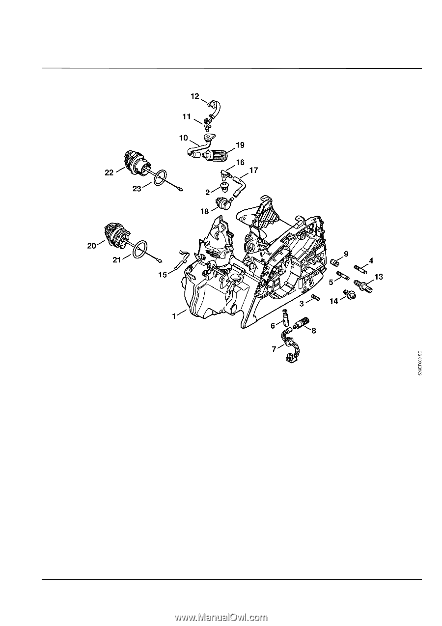
Drawing
A
Engine housing
MS 181, MS 181 C
1
SCS 01-2010 3.29