Stihl MS 211 C-BE Parts Diagram
Stihl MS 211 C-BE Manual
 |
View all Stihl MS 211 C-BE manuals
Add to My Manuals
Save this manual to your list of manuals |
Stihl MS 211 C-BE manual content summary:
- Stihl MS 211 C-BE | Parts Diagram - Page 1
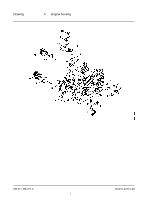
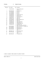
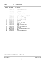
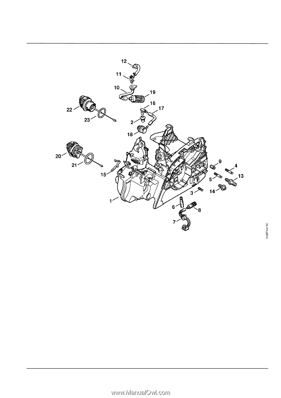
Drawing A Engine housing MS 211, MS 211 C 1 SCS 01-2010 3.29 - Stihl MS 211 C-BE | Parts Diagram - Page 2
1123 664 2400 14 1123 664 2402 15 1139 442 1600 16 1139 353 2700 17 0000 930 2803 18 0000 350 5802 1 Filler cap (1,3) ☐ 21 1 Oring 25x3.5 (1,3) 1 Filler cap (1,3) ☐ 23 1 Oring 23x3 (1,3) (1) MS 211, (2) MS 211 C-BE, (3) MS 211-Z, (4) MS 211 C-BE Z MS 211, MS 211 C 2 SCS 01-2010 3.29 - Stihl MS 211 C-BE | Parts Diagram - Page 3
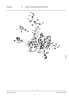
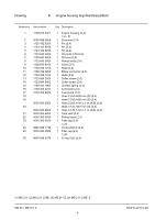
Drawing B Engine housing ErgoStart/Easy2Start MS 211, MS 211 C 3 SCS 01-2010 3.29 - Stihl MS 211 C-BE | Parts Diagram - Page 4
2402 15 1139 442 1600 16 1139 353 2701 17 4130 1 Collar screw (2,4) 1 Contact spring (2,4) 1 Connector (2,4) 1 Fuel pump (2,4) 1 Hose 2.2x5.4x38 mm (D) (2,4) 1 Hose (2,4) ☐ 26 1 Oring 23x3 (2,4) (1) MS 211, (2) MS 211 C-BE, (3) MS 211-Z, (4) MS 211 C-BE Z MS 211, MS 211 C 4 SCS 01-2010 3.29 - Stihl MS 211 C-BE | Parts Diagram - Page 5
Drawing C Cylinder, Muffler MS 211, MS 211 C 5 SCS 01-2010 3.29 - Stihl MS 211 C-BE | Parts Diagram - Page 6
2000 Qty Description 1 Cylinder with piston Ø 40 mm ☐ 2 - 6 1 Piston Ø 40 mm ☐ 3 - 5 2 Piston ring 16 1 Screen (3,4) USA, AUS, CDN 1 Cooling plate 2 Pan head self-tapping screw IS-D5x18 2 Plug 1 Tube of sealant Dirko HT red (1) MS 211, (2) MS 211 C-BE, (3) MS 211-Z, (4) MS 211 C-BE Z MS 211, MS 211 - Stihl MS 211 C-BE | Parts Diagram - Page 7
Drawing D Rewind starter MS 211, MS 211 C 7 SCS 01-2010 3.29 - Stihl MS 211 C-BE | Parts Diagram - Page 8
(1,3) 1 Starter grip ElastoStart Ø 3 mm (B) (1,3) ☐ 15, 16 1 Starter rope Ø 3x800 mm (B) (1,3) 1 Cap (B) (1,3) 1 Cover plate kit (B) (1,3) ☐ 17, 18 1 Cover plate (B) (1,3) 2 Self-tapping screw 3.9x13 (B) (1,3) (1) MS 211, (2) MS 211 C-BE, (3) MS 211-Z, (4) MS 211 C-BE Z MS 211, MS 211 C 8 SCS - Stihl MS 211 C-BE | Parts Diagram - Page 9
Drawing E Rewind starter ErgoStart/Easy2Start MS 211, MS 211 C 9 SCS 01-2010 3.29 - Stihl MS 211 C-BE | Parts Diagram - Page 10
1139 084 7800 1 Segment (2,4) 16 1139 967 1504 1 Model plate MS 211 C (2,4) 17 9074 477 4135 3 Pan head self-tapping screw IS-P5x20 (2,4) 18 9074 477 4139 1 Pan head self-tapping screw IS-P5x25 (2,4) (1) MS 211, (2) MS 211 C-BE, (3) MS 211-Z, (4) MS 211 C-BE Z MS 211, MS 211 C 10 SCS 01-2010 - Stihl MS 211 C-BE | Parts Diagram - Page 11
Drawing F Ignition system MS 211, MS 211 C 11 SCS 01-2010 3.29 - Stihl MS 211 C-BE | Parts Diagram - Page 12
2 Torsion spring (2,4) 2 E-clip 3.2 (2,4) 1 Ignition module ☐ 8, 9 1 Spark plug boot 1 Torsion spring 2 Pan head self-tapping screw IS-D4x18 1 Washer 4.3 1 Insulator 1 Lead retainer 1 Wiring harness (1) MS 211, (2) MS 211 C-BE, (3) MS 211-Z, (4) MS 211 C-BE Z MS 211, MS 211 C 12 SCS 01-2010 3.29 - Stihl MS 211 C-BE | Parts Diagram - Page 13
Drawing G Hand guard, Chain brake MS 211, MS 211 C 13 SCS 01-2010 3.29 - Stihl MS 211 C-BE | Parts Diagram - Page 14
tapping screw IS-D5x16 (1,3) 1 Chain sprocket cover (1,3) 1 Hexagon nut M8 (1,3) 1 Instruction label (3,4) USA 1 Chain catcher (20.2007) ☐ 35, 36 1 Countersunk screw M6x14 (20.2007) 1 Lock nut M6 (20.2007) (1) MS 211, (2) MS 211 C-BE, (3) MS 211-Z, (4) MS 211 C-BE Z MS 211, MS 211 C 14 SCS 01-2010 - Stihl MS 211 C-BE | Parts Diagram - Page 15
Drawing H Quick chain tensioner MS 211, MS 211 C 15 SCS 01-2010 3.29 - Stihl MS 211 C-BE | Parts Diagram - Page 16
1000 Qty Description 1 Quick tensioner parts (B) ☐ 1 - 15 1 Chain sprocket cover (2,4) ☐ 2 - 4 1 Cover plate (2,4) 1 Adjusting wheel (2,4) 1 Pan head self- IS-D5x16 (2,4) 1 Screwdriver T27x120x70 (B) (1) MS 211, (2) MS 211 C-BE, (3) MS 211-Z, (4) MS 211 C-BE Z MS 211, MS 211 C 16 SCS 01-2010 3.29 - Stihl MS 211 C-BE | Parts Diagram - Page 17
Drawing J Air filter, Manifold MS 211, MS 211 C 17 SCS 01-2010 3.29 - Stihl MS 211 C-BE | Parts Diagram - Page 18
S120B (2,4) 11 1139 120 0901 1 Carburetor bracket ☐ 12 12 1139 121 2501 1 Slide 13 1139 141 1801 1 Sleeve 14 1139 140 2500 1 Manifold 15 9075 478 3012 4 Pan head self-tapping screw IS-D4x12 (1) MS 211, (2) MS 211 C-BE, (3) MS 211-Z, (4) MS 211 C-BE Z MS 211, MS 211 C 18 SCS 01-2010 3.29 - Stihl MS 211 C-BE | Parts Diagram - Page 19
Drawing K Carburetor C1Q-S119B MS 211, MS 211 C 19 SCS 01-2010 3.29 - Stihl MS 211 C-BE | Parts Diagram - Page 20
Description 1 Carburetor C1Q-S119B (1,3) ☐ 1 - 40 1 1139 122 7402 1 Round head screw (1,3) 16 1120 122 6601 4 Collar screw (1,3) adjustment screw (1,3) 21 1139 122 6700 1 High speed adjustment screw MS 211, (2) MS 211 C-BE, (3) MS 211-Z, (4) MS 211 C-BE Z MS 211, MS 211 C 20 SCS 01-2010 3.29 - Stihl MS 211 C-BE | Parts Diagram - Page 21
Drawing K Carburetor C1Q-S119B MS 211, MS 211 C 21 SCS 01-2010 3.29 - Stihl MS 211 C-BE | Parts Diagram - Page 22
2 E-clip (1,3) 1 Throttle lever (1,3) 1 Torsion spring (1,3) 1 Throttle lever (1,3) 1 Flat head screw M3x3.5 (1,3) 1 Idle speed adjustment screw (1,3) 1 Set of carburetor parts (1,3) ☐ 8, 9, 26, 27 (1) MS 211, (2) MS 211 C-BE, (3) MS 211-Z, (4) MS 211 C-BE Z MS 211, MS 211 C 20 SCS 01-2010 3.29 - Stihl MS 211 C-BE | Parts Diagram - Page 23
Drawing L Carburetor C1Q-S120B MS 211, MS 211 C 23 SCS 01-2010 3.29 - Stihl MS 211 C-BE | Parts Diagram - Page 24
Description 1 Carburetor C1Q-S120B (2,4) ☐ 1 - 40 1 1139 122 7402 1 Round head screw (2,4) 16 1120 122 6601 4 Collar screw (2,4) adjustment screw (2,4) 21 1139 122 6700 1 High speed adjustment screw MS 211, (2) MS 211 C-BE, (3) MS 211-Z, (4) MS 211 C-BE Z MS 211, MS 211 C 24 SCS 01-2010 3.29 - Stihl MS 211 C-BE | Parts Diagram - Page 25
Drawing L Carburetor C1Q-S120B MS 211, MS 211 C 25 SCS 01-2010 3.29 - Stihl MS 211 C-BE | Parts Diagram - Page 26
2 E-clip (2,4) 1 Throttle lever (2,4) 1 Torsion spring (2,4) 1 Throttle lever (2,4) 1 Flat head screw M3x3.5 (2,4) 1 Idle speed adjustment screw (2,4) 1 Set of carburetor parts (2,4) ☐ 8, 9, 26, 27 (1) MS 211, (2) MS 211 C-BE, (3) MS 211-Z, (4) MS 211 C-BE Z MS 211, MS 211 C 24 SCS 01-2010 3.29 - Stihl MS 211 C-BE | Parts Diagram - Page 27
Drawing M Handle frame, Shroud MS 211, MS 211 C 27 SCS 01-2010 3.29 - Stihl MS 211 C-BE | Parts Diagram - Page 28
0000 967 3662 1 Warning pictogram MS 4 0000 967 3500 1 Instruction label (3,4) USA 5 0000 791 Throttle trigger 15 1117 182 4500 1 Torsion spring 16 1139 182 0800 1 Trigger interlock 17 1139 791 MS 211, (2) MS 211 C-BE, (3) MS 211-Z, (4) MS 211 C-BE Z MS 211, MS 211 C 28 SCS 01-2010 3.29 - Stihl MS 211 C-BE | Parts Diagram - Page 29
Drawing N Tools, Extras MS 211, MS 211 C 29 SCS 01-2010 3.29 - Stihl MS 211 C-BE | Parts Diagram - Page 30
0000 792 9152 4 0812 370 1000 5 0000 891 0801 6 1110 893 4000 Qty Description 1 Combination wrench 1 Screwdriver 1 Chain scabbard 1 Screwdriver T27x120x70 (B) 1 Tool roll (B) 1 Filing gauge (B) (1) MS 211, (2) MS 211 C-BE, (3) MS 211-Z, (4) MS 211 C-BE Z MS 211, MS 211 C 30 SCS 01-2010 3.29
-
 1
1 -
 2
2 -
 3
3 -
 4
4 -
 5
5 -
 6
6 -
 7
7 -
8
-
9
-
10
-
11
-
12
-
13
-
14
-
15
-
16
-
17
-
18
-
19
-
20
-
21
-
22
-
23
-
24
-
25
-
26
-
27
-
28
-
29
-
30
 |
 |
Drawing
A
Engine housing
MS 211, MS 211 C
1
SCS 01-2010 3.29