Thermador CIT365GM Installation Instructions
Thermador CIT365GM Manual
 |
View all Thermador CIT365GM manuals
Add to My Manuals
Save this manual to your list of manuals |
Thermador CIT365GM manual content summary:
- Thermador CIT365GM | Installation Instructions - Page 1
INSTALLATION INSTRUCTIONS For Induction Cooktop Model: CIT304... CIT365... Installation Instructions Instuctions d'Installation Instrucciones de Instalación 3 - 13 14 - 24 25 - 35 - Thermador CIT365GM | Installation Instructions - Page 2
Safety Instructions 4 Before you begin 5 Tools and parts needed 5 Parts included 5 Preparation 6 Installation procedure 9 Installing the heat shield 9 Secure the cooktop to countertop 10 Electrical installation 11 Test the installation 12 Technical service - Thermador CIT365GM | Installation Instructions - Page 3
property damage or personal injury. ř WARNING:ĄDo not repair or replace any part of the appliance unless specifically recommended in the manual. Never modify or alter the construction of the appliance. Improper installation, technical service or maintenance can cause injury or property damage. Refer - Thermador CIT365GM | Installation Instructions - Page 4
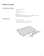
Before you begin Tools and parts needed Parts included D Phillips head screwdriver D Pencil D Drill with 1/4" (6.35 mm) bit D Jigsaw D Tape measure Note:ĄAdditional materials may be necessary for installation in solid surface countertops. Contact the countertop manufacturer. D Hold down brackets - Thermador CIT365GM | Installation Instructions - Page 5
cutout to make them heat resistant. This prevents the surfaces from expanding as a result of humidity. Solid surface countertops often require special installation. For example, heat reflective tape or rounded corners may be necessary. Contact the countertop manufacturer for instructions specific - Thermador CIT365GM | Installation Instructions - Page 6
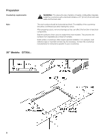
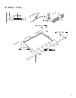
36" Models: CIT365... 7 - Thermador CIT365GM | Installation Instructions - Page 7
The distance from the top of the cooktop to the bottom of the cabinets above it must be A = 30" (762 mm) minimum. This distance 0.020" (0.5 mm) thick copper, at a minimum. Verify that the cabinets above the cooktop are a maximum of B=13" (330 mm) deep. Cabinet bottom (unprotected) Building back - Thermador CIT365GM | Installation Instructions - Page 8
the plate. For safety reasons, the heat shield must be properly installed. This prevents components from overheating as a result of the recirculation of hot air from the cooktop. The heat shield is the same width as the cooktop. For shipping, it is screwed to the burner box. After unpacking - Thermador CIT365GM | Installation Instructions - Page 9
place and that it needs to be supported along a broad area of the edges when placing" the cooktop into the cutout. The cooktop should be secured to the countertop using the clamping brackets provided. Before inserting the cooktop into the cutout, turn the cooktop upside down and attach brackets to - Thermador CIT365GM | Installation Instructions - Page 10
Electrical installation Electrical requirements You can find the identification plate with the electrical specifications on the underside of the appliance. The junction box must be located within 3 feet (~900 mm) of the cooktop connection. It should be easily accessible for service purposes. 3 1/4" - Thermador CIT365GM | Installation Instructions - Page 11
Electrical connection ř CAUTION:ĄBefore installing, turn off at the service panel. Lock service panel to prevent power from wire Certified UL connector Junction box Grounded green cable Cooktop power supply cord If the cooktop is installed and connected as specified above, it will be - Thermador CIT365GM | Installation Instructions - Page 12
Contact our Technical Service Department if your appliance needs repair. Our central Customer Service Center (see below) will also be happy to supply you with details on a center close to you. When you contact our customer service, have the product (E) number and the manufacturing (FD) number - Thermador CIT365GM | Installation Instructions - Page 13
matières Instructions de sécurité importantes 15 Avant de commencer 16 Outils et pièces nécessaires 16 Pièces incluses 16 Préparation 17 Procédure d'installation 20 Installation du déflecteur métallique 20 Fixer la plaque au plan de travail 21 Installation électrique - Thermador CIT365GM | Installation Instructions - Page 14
. CET APPAREIL DOIT ÊTRE INSTALLÉ PAR UN TECHNICIEN QUALIFIÉ UN FOIS L'INSTALLATION TERMINÉE, GARDER CES INSTRUCTIONS AVEC L'APPAREIL MÉNAGER. Sécurité électrique Avant de procéder à l'installation, éteindre le disjoncteur du panneau de service. Verrouiller le disjoncteur pour éviter que le courant - Thermador CIT365GM | Installation Instructions - Page 15
installée par un spécialiste, conformément aux instructions d'installation. L'installateur est responsable de tout dommage qui résulterait d'une installation pour l'installation sur des surfaces de travail solides. Prendre contact avec le fabricant de la surface de travail. D Supports de fixation - Thermador CIT365GM | Installation Instructions - Page 16
:ĄPour réduire le risque d'incendie de matériaux combustibles environnants, installer le plan de travail à une distance d'au moins 51 mm. ée à l'humidité. Les plans de travail solides requièrent fréquemment des installations spéciales. Par exemple, ces matériaux requièrent parfois l'utilisation de - Thermador CIT365GM | Installation Instructions - Page 17
36" Modèles : CIT365... 18 - Thermador CIT365GM | Installation Instructions - Page 18
Critères des armoires La distance de la partie supérieure de la plaque à la partie inférieure des cabinets situés au-dessus sera de A = 762 mm. au minimum. Cette distance peut être réduite à A = 610 mm., quand la partie inférieure de l'armoire en bois ou en métal est protégée par un carton ré - Thermador CIT365GM | Installation Instructions - Page 19
ř AVERTISSEMENT:ĄUtiliser des gants de protection pour procéder à l'installation de la plaque. Installation du déflecteur métallique Pour des raisons de sécurité, le déflecteur métallique doit être installé correctement. Ceci afin d'éviter la recirculation de l'air chaud en provenance - Thermador CIT365GM | Installation Instructions - Page 20
Fixer la plaque au plan de travail Ne laissez pas "tomber" le verre de la plaque sur son emplacement, il doit être supporté sur tout son périmètre par une large surface des bords au moment de placer" la table de cuisson sur la découpe. La plaque doit ê - Thermador CIT365GM | Installation Instructions - Page 21
Installation électrique Critères électriques Ces caractéristiques techniques figurent sur la plaque d'identification au bas de l'appareil ménager. Le boîtier de dérivation doit être - Thermador CIT365GM | Installation Instructions - Page 22
Branchement électrique Tester l'installation ř ATTENTION:ĄAvant l'installation, éteindre le disjoncteur du panneau de service. Attacher le disjoncteur pour empêcher qu'il allume accidentellement l'alimentation électrique. La capacité maximum en ampères des disjoncteurs dérivés, la taille des câbles - Thermador CIT365GM | Installation Instructions - Page 23
sera ravi de vous référer à un centre près de votre domicile. Lorsque vous appelez notre service à la clientèle, ayez à votre disposition le numéro de produit (E) et le numéro recevoir de vos nouvelles très bientôt ! 1-800-735-4328 www.thermador.com 5551 McFadden Ave. Huntington Beach, CA 92649 24 - Thermador CIT365GM | Installation Instructions - Page 24
Contenido Instrucciones de seguridad importantes 26 Antes de empezar 27 Herramientas y piezas necesarias 27 Piezas incluidas 27 Preparación 28 Procedimiento de instalación 31 Instalación del deflector metálico 31 Asegure la placa a la superficie de trabajo 32 - Thermador CIT365GM | Installation Instructions - Page 25
que puede causar daños materiales o lesiones personales. ř AVISO:ĄNo repare ni reemplace ninguna parte del electrodoméstico, a menos que esté específicamente recomendado en este manual. Nunca modifique ni altere la construcción del electrodoméstico. La instalación, servicio técnico o mantenimiento - Thermador CIT365GM | Installation Instructions - Page 26
puede reducir el riesgo instalando una campana que se proyecte horizontalmente 5 pulgadas (12.7 cm) como mínimo de la parte inferior del gabinete. No instale refrigeradores, lavavajillas, hornos sin sistemas de ventilación ni lavadoras que puedan caber debajo de la placa. Advertencia:ĄRecomendamos - Thermador CIT365GM | Installation Instructions - Page 27
de la superficie de trabajo AVISO:ĄPara reducir el riesgo de ignición de materiales combustibles circundantes, instale la superficie de trabajo con una distancia de, al menos, 2" (51 mm) de ambas trabajo, comuníquese con el fabricante de la superficie de trabajo. 30" Modelos: CIT304... 28 - Thermador CIT365GM | Installation Instructions - Page 28
36" Modelos: CIT365... 29 - Thermador CIT365GM | Installation Instructions - Page 29
Requisitos de gabinetes La distancia desde la parte superior de la placa hasta la parte inferior de los gabinetes que se encuentran arriba deberá ser A = 30" (762 mm) como mínimo. Esta distancia se puede reducir a A = 24" (610 mm), cuando la parte inferior del gabinete de madera o metal está - Thermador CIT365GM | Installation Instructions - Page 30
Procedimiento de instalación Instalación del deflector metálico ř AVISO:ĄUse guantes de protección al instalar la placa. Por razones de seguridad, el deflector metálico debe instalarse correctamente. De esta forma, se impide la recirculación de aire caliente procedente de la placa de cocción, y se - Thermador CIT365GM | Installation Instructions - Page 31
Asegure la placa a la superficie de trabajo No "dejar caer" el vidrio de la placa en su ubicación, debe sujetarse en todo su perímetro por una superficie amplia de los bordes en el momento de "instalar" la placa de cocción en su hueco. La placa debe asegurarse a la superficie de trabajo con los - Thermador CIT365GM | Installation Instructions - Page 32
Instalación eléctrica Requisitos eléctricos Puede encontrar la placa de identificación con las especificaciones eléctricas en la parte inferior del electrodoméstico. La caja de conexiones debe estar ubicada dentro de los 3 pies (~900 mm) de la conexión de la placa. Se debe - Thermador CIT365GM | Installation Instructions - Page 33
Conexión eléctrica ř ATTENCION:ĄAntes de la instalación, apague el disyuntor de la caja de fusibles. Trabe el disyuntor para impedir que se encienda accidentalmente la alimentación eléctrica. La capacidad máxima en amperios de los disyuntores de los circuitos derivados, el tamaño de los cables y - Thermador CIT365GM | Installation Instructions - Page 34
ón (FD) de su electrodoméstico. Puede encontrar la placa de identificación con estos números en la parte inferior del electrodoméstico. ¿Preguntas? Comuníquese con nosotros. ¡Esperamos tener noticias suyas pronto! 1-800-735-4328 www.thermador.com 5551 McFadden Ave. Huntington Beach, CA 92649 35 - Thermador CIT365GM | Installation Instructions - Page 35
9000309460 (1W09NA) 02 8903 5551 McFadden Avenue, Huntington Beach, CA 92649 S 1Ć800Ć735Ć4328 Swww.thermador.com E BSH Home Appliances Corporation 2005
-
 1
1 -
 2
2 -
 3
3 -
 4
4 -
 5
5 -
 6
6 -
 7
7 -
8
-
9
-
10
-
11
-
12
-
13
-
14
-
15
-
16
-
17
-
18
-
19
-
20
-
21
-
22
-
23
-
24
-
25
-
26
-
27
-
28
-
29
-
30
-
31
-
32
-
33
-
34
-
35
 |
 |

Model:
CIT304...
Installation Instructions
3 - 13
Instuctions d'Installation
14 - 24
Instrucciones de
Instalación
25 - 35
INSTALLATION
INSTRUCTIONS
For Induction Cooktop
CIT365...