Thermador PRD364EDPG Installation Instructions
Thermador PRD364EDPG Manual
 |
View all Thermador PRD364EDPG manuals
Add to My Manuals
Save this manual to your list of manuals |
Thermador PRD364EDPG manual content summary:
- Thermador PRD364EDPG | Installation Instructions - Page 1
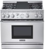
INSTALLATION INSTRUCTIONS For Thermador Professional® PRO-GRANDTM Dual Fuel Ranges INSTRUCTIONS D'INSTALLATION Pour toutes les cuisinières mixtes Thermador Professional® PRO-GRANDTM Models PD30 PD36 PD48 - Thermador PRD364EDPG | Installation Instructions - Page 2
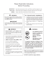
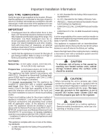
fire department. - Installation and service must be performed by a qualified installer, service agency or the gas supplier. WARNING ■ ALL RANGES CAN TIP ■ INJURY TO PERSONS COULD RESULT ■ INSTALL ANTI-TIP DEVICE ■ SEE INSTALLATION INSTRUCTIONS TO REDUCE THE RISK OF TIPPING OF THE APPLIANCE, IT MUST - Thermador PRD364EDPG | Installation Instructions - Page 3
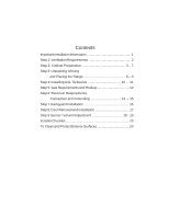
Information 1 Step 1: Ventilation Requirements 2 Step 2: Cabinet Preparation 3 - 7 Step 3: Unpacking, Moving and Placing the Range 8 - 9 Step 4: Installing Anti-Tip Device 10 - 11 Step 5: Gas Requirements and Hookup 12 Step 6: Electrical Requirements, Connection and Grounding 13 - 15 - Thermador PRD364EDPG | Installation Instructions - Page 4
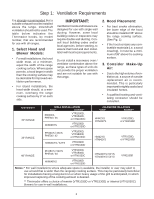
or standards apply to specific installations. This appliance is equipped with an intermittent/interrupted ignition device that cycles the two far left surface burners on and off when in the ExtraLow® setting. Due to the high heat of the cooktop burners, installing a microwave oven with a ventilation - Thermador PRD364EDPG | Installation Instructions - Page 5
building codes or inspectors may require double wall ducting. Consult local building codes and/or local agencies, before starting, to assure that hood and duct installation will meet local requirements. Do not install a microwave oven / ventilator combination above the range, as these types of units - Thermador PRD364EDPG | Installation Instructions - Page 6
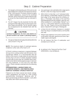
a space wide enough to accept the flared island hood, as indicated in Fig. 1. 2. The 36" ranges may be recessed into the cabinets beyond the edge of the front face of the oven (See Figures 2A and 2B). The 30" and 48" ranges are not approved to be installed flush with the cabinets. CAUTION In these - Thermador PRD364EDPG | Installation Instructions - Page 7
Do not install the 30" and 48" ranges such that the oven door is flush with the cabinet face. A flush installation could result in damage to the cabinets due to exposure to high heat. ® ® ® } } } FIG. 1 Cabinet Clearances For 30" Ranges For 36" Ranges For 48" Ranges 30" or 36" Wide Hood 36" or - Thermador PRD364EDPG | Installation Instructions - Page 8
Pot and Pan Shelf 3/8" FIG. 2B - Side View with Island Trim 4" ® ® 5 NOTE: For Island Trim installations, counter surface should have a cantilever edge meeting the back section of the island trim accessory. Cantilever Countertop NOTE: If an inner wall is used under the cantilever counter top - Thermador PRD364EDPG | Installation Instructions - Page 9
all users know where and how to shut off the gas supply to the range. NOTE: The installer should inform the consumer of the location of the gas shut-off valve. 3/4" Flex Line to Appliance ® ® ® Gas Supply Zone A® 1/2" NPT B 240 VAC Receptacle (Shown) or Junction Box Centerline of Electrical - Thermador PRD364EDPG | Installation Instructions - Page 10
Step 2: Cabinet Preparation ELECTRICAL SUPPLY Installation of the range must be planned so that the rough-in of box in the wall will be directly behind the junction box on the unit when the unit is installed. Refer to Figure 8 on Page 14 for location of junction box on unit. To minimize binding - Thermador PRD364EDPG | Installation Instructions - Page 11
the installer to remove two screws holding each bracket then remove bracket and reinstall screws. Chart A 30" Range 36" Range Shipping Weight Weight without packing materials Without door(s), burner caps, front kick panel and oven racks 335 lbs. 285 lbs. 215 lbs. 444 lbs. 390 lbs. 295 lbs. 48 - Thermador PRD364EDPG | Installation Instructions - Page 12
for all products that have the griddle feature). The range is leveled by adjusting the legs with a wrench. • Replace the kick panel and install the oven Remove all tape and packaging before using the door. To install door, see Page 17. Do not appliance. Destroy the packaging after unpackinstall the - Thermador PRD364EDPG | Installation Instructions - Page 13
attach it to the floor, wall or cabinet by installing the Anti-Tip Device supplied. • A risk of tip-over may exist if the appliance is not installed in accordance with these instructions. • If the range is pulled away from the wall for cleaning, service or any other reason, ensure that the Anti-Tip - Thermador PRD364EDPG | Installation Instructions - Page 14
Anti-Tip Device 30 and 36 Inch Ranges (Figures 7A and 7B) Thermador Service Part No. Qty 415078 4 487310 1 Description Screw, Phillips, #10 x 1-1/2" Anti-Tip Bracket, Floor-Mounted IMPORTANT INSTALLATION INFORMATION: • The anti-tip bracket may be attached to a solid wood cabinet having - Thermador PRD364EDPG | Installation Instructions - Page 15
installer must do the conversion. Make certain the range matches the type of gas available at this location. The field conversion kit for this series of dual-fuel ranges is Thermador Model PLPKIT. Obey all instructions UP • A manual gas shut-off valve must be installed external to the appliance, in a - Thermador PRD364EDPG | Installation Instructions - Page 16
in the toe kick area of the range for access by a qualified service technician. • The ranges are to be connected to a 240/208 VAC power supply. CAUTION The appliance must be isolated from the gas supply piping system by closing its individual manual shutoff valve during any pressure testing of - Thermador PRD364EDPG | Installation Instructions - Page 17
• 3-CONDUCTOR CORD - Flexible electrical conduit or 4-connector Appliance Cord • PERMANENT CONNECTION WHERE LOCAL CODES AND (HARD WIRING) . 9. The FOR USE WITH RANGES. conduit must be installed to the junction box using an approved conduit connector. Installer - show the owner the location - Thermador PRD364EDPG | Installation Instructions - Page 18
may be connected to the terminal block. 3-WIRE LEAD CONNECTION 1. Remove upper nuts only from the terminal block studs. Do not remove nuts which secure range internal wiring leads. 2. Secure the neutral, grounded wire of the supply circuit, to the center stud of the terminal block with nut. (See Fig - Thermador PRD364EDPG | Installation Instructions - Page 19
Fig. 13, into the guide channels on the back of the range. Secure the backguard with the (4) sheet metal screws provided. FIG. 13 Front of Unit WARNING To avoid possible burn or fire hazard, a backguard designed specifically for this range must be installed whenever the range is used. ®® CAUTION - Thermador PRD364EDPG | Installation Instructions - Page 20
to test the movement and the fit of the door to the oven cavity. Do not force the door to open or close. If the door is properly installed, it should move smoothly and rest straight on the front of the range when closed. • If the door does not operate correctly, verify that - Thermador PRD364EDPG | Installation Instructions - Page 21
appliance, verify that the unit and the gas supply have been carefully checked for leaks and that the unit has been connected to the electrical power supply. Turn the manual do not carry over, call Thermador®. The two rangetop burners on knob is set to the XLO range. This is normal operation. Repeat - Thermador PRD364EDPG | Installation Instructions - Page 22
and perform flame evaluation. The air shutter must fit over the orifice hood for proper operation of the burner. • Repeat procedure as needed until void the appliance's warranty. Allow burners to cool before attempting to remove them! Call Thermador® if: 1. Any of the burners do not light. 2. Any - Thermador PRD364EDPG | Installation Instructions - Page 23
and with other burners operating. ❑ Oven door hinges seated and door alignment is in proper position. Door opens and closes properly. ❑ Burner grates correctly positioned. ❑ INSTALLER: Leave the Care and Use Manual and Installation Instructions with the owner of the appliance. To Clean and Protect - Thermador PRD364EDPG | Installation Instructions - Page 24
NOTES - Thermador PRD364EDPG | Installation Instructions - Page 25
gaz de chez un voisin. Suivez les instructions de la compagnie. ■ Si vous n'arrivez pas à contacter votre compagnie de gaz, appelez les pompiers. - L'installation et les réparations doivent être réalisées par un installateur qualifié, un centre de service agréé ou la compagnie de gaz. AVERTISSEMENT - Thermador PRD364EDPG | Installation Instructions - Page 26
12 Chapitre 6 : Exigences pour l'alimentation électrique, le branchement et la mise à la terre 13 - 15 Chapitre 7 : Installation de la plaque de protection ........ 16 Chapitre 8 : Enlever et installation de la porte 17 Chapitre 9 : Test et réglage de brûler 18 - 19 Liste de vérification de - Thermador PRD364EDPG | Installation Instructions - Page 27
basse Thermador doit être commandée séparément et installée à l'arrière de la cuisinière. Pour les installations en îlot et autres installations avec dernière édition. Au Canada, l'installation doit être conforme à CAN 1- B149.1 and .2, Code d'installation pour les appareils à combustion à - Thermador PRD364EDPG | Installation Instructions - Page 28
èle, les hottes Thermador qu'il est conseillé d'utiliser avec les cuisinières. 1. Choix du modèle de hotte et de ventilateur • Pour les installations murales, la largeur locales du secteur du bâtiment exigent toutefois une double conduite. Consultez les normes applicables et/ou l'administration - Thermador PRD364EDPG | Installation Instructions - Page 29
installations en îlot, excepté pour les armoires suspendues qui doivent laisser un espace suffisamment grand 48") ne sont pas homologuées pour être installées à ras des armoires. MISE EN GARDE Dans ce type d'installation 12"), il est obligatoire d'installer une plaque Thermador de protection arrière, - Thermador PRD364EDPG | Installation Instructions - Page 30
cm (36") ou 106,7 cm (42") 106,7 cm (42") ou 121,9 cm (48") pour installation en îlot Cuisinière de 121,9 cm (48 ") Hotte de 121,9 cm (48") , 137,2 cm (54") ou 152,4 cm (60") 121,9 cm (48") ou 137,2 cm (54") pour installation en îlot ® ® ® } } } ® ® 45,8 cm (18") min. 91,4 cm (36") entre le - Thermador PRD364EDPG | Installation Instructions - Page 31
(ANSI Z223.1, Version actuelle). FIG. 2B - Vue latérale Min. 30,48 cm (12") à combustibles avec enjoliveur pour îlot. Min. 91,4 cm ( à combustibles Enjoliveur pour îlot 4" ® ® Matériaux combustibles REMARQUE : Pour installer l'enjoliveur pour îlot, le plan de travail doit avoir un bord en porte - Thermador PRD364EDPG | Installation Instructions - Page 32
et de zone de gaz est acceptable. REMARQUE : Si non déjà en place, installer une soupape d'arrêt de gaz dans un endroit Zone d'arrivée du gaz A® plus du détendeur fourni avec la cuisinière (voir Chapitre 5). l'installateur doit 48" 41,9cm 40,6cm 39,4cm 16,5cm 13,3cm aviser le consommateur de - Thermador PRD364EDPG | Installation Instructions - Page 33
: Préparation de l'emplacement ALIMENTATION ÉLECTRIQUE L'installation des cuisinières doit être planifiée de sorte murale se trouve juste derrière la boîte de dérivation de l'appareil une fois celui-ci installé. Reportez-vous à la Figure 8 de la page 14 pour l'emplacement de la boîte de - Thermador PRD364EDPG | Installation Instructions - Page 34
acier. Tableau A Cuisinière de 76,2 cm (30") Cuisinière de 91,4 cm (36") Cuisinière de 121,9 cm (48") Poids à l'expédition 152 kg (335 lb) 201,4 kg (444 lb) 264,9 kg (584 lb) Poids sans mat protéger le fini des égratignures jusqu'à ce que l'appareil soit installé à sa position permanente. 8 - Thermador PRD364EDPG | Installation Instructions - Page 35
roulettes Le poids de la cuisinière doit être uniformément réparti en s'aidant des supports placés sur le dessous de la cuisinière 57,8 cm (22-3/4") • Pour un matériel d'emballage et le ruban adhésif la porte du four. Pour installer la porte, voir la avant d'utiliser l'appareil. Détruire le matériel - Thermador PRD364EDPG | Installation Instructions - Page 36
et de 91,4 cm (36"), un dispositif antibascule doit être installé conformément aux instructions suivantes. AVERTISSEMENT DANGER DE RENVERSEMENT • Toutes les cuisinières peuvent se (3/16"), cloison en préfabriqué ou béton, 4 (inutile si le support de montage est fixé sur du bois dur ou du métal) 10 - Thermador PRD364EDPG | Installation Instructions - Page 37
de 30" et 36" (Figures 7A et 7B) Référence pièce détachée Thermador 415078 487310 Quantité 4 1 Description Vis Phillips no 10 x 1-1/2" La patte antibascule, montage au sol INFORMATIONS IMPORTANTES À PROPOS DE L'INSTALLATION : • La patte antibascule peut être fixée à une armoire en bois massif - Thermador PRD364EDPG | Installation Instructions - Page 38
ée, gamme DP, est le produit PLKIT de Thermador. Observer toutes les instructions fournies avec ce nécessaire pour effectuer correctement la la colonne d'eau) RACCORDEMENT • Un robinet manuel d'arrêt de gaz doit être installé à l'extérieur de l'appareil, à un endroit accessible par le devant, dans - Thermador PRD364EDPG | Installation Instructions - Page 39
correspondant. Verrouiller le panneau de service pour empêcher la mise és à l'alimentation électrique au moyen d'une installation fixe ou du cordon d'alimentation, comme décrit des circuits d'alimentation électrique TYPE DE MODÈLE 30" 36" 48" TENSION 240/208 VCA 240/208 VCA 240/208 VCA COURANT 35 - Thermador PRD364EDPG | Installation Instructions - Page 40
à le débrancher de la source d'alimentation. La longueur minimum recommandée de cordon ou de conduite est de 1,22 m (quatre pieds). Les installations électriques et la mise à la terre doivent être conformes à l'ensemble des réglementations locales et/ou au Code national de l'électricité, selon ce - Thermador PRD364EDPG | Installation Instructions - Page 41
® ® ® ® ®® ® ® Chapitre 6 : Conditions d'alimentation, branchement et mise à laterre Il est possible de connecter une alimentation à 3 ou à 4 conducteurs sur la plaque à bornes. FIG. 9 Fixation des conducteurs Écrou supérieur Rondelle à collerette Connexion à 3 fils 1. Retirez seulement les é - Thermador PRD364EDPG | Installation Instructions - Page 42
5). Une garniture pour îlot est disponible pour couvrir les rebords de fixation du dosseret pour les installations en îlot, où il y a un dégagement minimum de 12 po derrière la garniture ENJOLIVEUR POUR ÎLOT 30" Inclus 36" N/D 48" N/D N/D LB36R LB48R HS30R HS36R HS48R IT30R IT36R IT48R 16 - Thermador PRD364EDPG | Installation Instructions - Page 43
• La porte est lourde et fragile. Utiliser les deux mains pour enlever ou installer la porte. • Saisir seulement les extrémités de la poignée de la Les charnières s'enclenchent de façon sécuritaire dans les fentes lorsque bien installées. Ne pas forcer, plier ni tordre la porte. Conseil: déposer - Thermador PRD364EDPG | Installation Instructions - Page 44
et le brûleur. Si les brûleurs ne sont pas enveloppés, communiquer avec Thermador®. Les 2 brûleurs de surface du côté gauche sont dotés de la fonction requièrent habituellement pas d'autre réglage sauf dans les cas d'installation à haute altitude. Si un réglage de brûleur/flamme est requis, voir la - Thermador PRD364EDPG | Installation Instructions - Page 45
voir figure 15). • Serrer la vis d'obturateur • Après le réglage, réinstaller le brûleur et vérifier la flamme. L'obturateur d'air doit s'ajuster sur de l'appareil. Laisser les brûleurs refroidir avant de les enlever ! Communiquer avec Thermador® si : 1. Un brûleur ne s'allume pas. 2. Si un brûleur - Thermador PRD364EDPG | Installation Instructions - Page 46
les matériaux d'emballage ont été retirés. ❑ Garniture d'îlot ou dosseret installé selon les instructions. ❑ La plaque d'habillage a été posée et fixée par deux correctement. ❑ INSTALLATEUR : laisser les GUIDES D'UTILISATION et D'ENTRETIEN et D'INSTALLATION avec le propriétaire. Nettoyage et - Thermador PRD364EDPG | Installation Instructions - Page 47
REMARQUES - Thermador PRD364EDPG | Installation Instructions - Page 48
the most detailed information, refer to installation instructions accompanying product or write Thermador indicating model number. We reserve the right to change specifications or design without notice. Some models are certified for use in Canada. Thermador is not responsible for products which are
-
 1
1 -
 2
2 -
 3
3 -
 4
4 -
 5
5 -
 6
6 -
 7
7 -
8
-
9
-
10
-
11
-
12
-
13
-
14
-
15
-
16
-
17
-
18
-
19
-
20
-
21
-
22
-
23
-
24
-
25
-
26
-
27
-
28
-
29
-
30
-
31
-
32
-
33
-
34
-
35
-
36
-
37
-
38
-
39
-
40
-
41
-
42
-
43
-
44
-
45
-
46
-
47
-
48
 |
 |

INSTALLATION
INSTRUCTIONS
For Thermador
Professional
®
PRO-GRAND
TM
Dual Fuel Ranges
Models
PD30
PD36
PD48
Pour toutes les cuisinières mixtes
Thermador Professional
®
PRO-GRAND
TM
INSTRUCTIONS
D’INSTALLATION