Thermador PRD364GDHU Installation Instructions
Thermador PRD364GDHU Manual
 |
View all Thermador PRD364GDHU manuals
Add to My Manuals
Save this manual to your list of manuals |
Thermador PRD364GDHU manual content summary:
- Thermador PRD364GDHU | Installation Instructions - Page 1
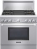
MANUAL For Thermador Professional® PRO-HARMONY™ Dual Fuel Ranges MANUEL D'INSTALLATION Pour toutes les cuisinières mixtes Thermador Professional® PRO-HARMONY™ Models/ Modèles / Modelos: PRD30 PRD36 PRD48 MANUAL DE INSTALACIÓN Para Estufas de Todo Tipo de Gas Thermador Professional® PRO-HARMONY - Thermador PRD364GDHU | Installation Instructions - Page 2
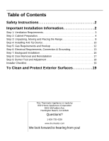
16 Step 8: Door Removal and Reinstallation 17 Step 9: Burner Test and Adjustment 18 Installer Checklist 19 To Clean and Protect Exterior Surfaces 19 This Thermador Appliance is made by BSH Home Appliances Corporation 5551 McFadden Ave. Huntington Beach, CA 92649 Questions? 1-800-735-4328 www - Thermador PRD364GDHU | Installation Instructions - Page 3
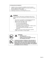
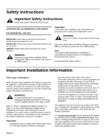
must be performed by a qualified installer, service agency or the gas supplier. WARNING • All Ranges can tip • Injury to Persons could result • Install Anti-Tip Device packaged with range • See Installation Instructions TO REDUCE THE RISK OF TIPPING OF THE APPLIANCE, IT MUST BE SECURED BY A PROPERLY - Thermador PRD364GDHU | Installation Instructions - Page 4
the back edge of the range. A Thermador backguard must be ordered separately and installed at the rear of the range. A Low Back is supplied with the 30" model, and all other models are supplied with a Flush Island Trim. For island installations and other installations with more than 12" clearance - Thermador PRD364GDHU | Installation Instructions - Page 5
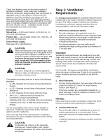
building codes or inspectors may require double wall ducting. Consult local building codes and/or local agencies, before starting, to assure that hood and duct installation will meet local requirements. Do not install a microwave oven/ventilator combination above the range, as these type of units do - Thermador PRD364GDHU | Installation Instructions - Page 6
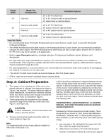
have a space wide enough to accept the flared island hood, as indicated in Figure 1. 2. These ranges may be recessed into the cabinets beyond the edge of the front face of the oven (See Figure 2 and Figure 3b). CAUTION In these installations, the door and cabinet can cause a pinching hazard. 3. The - Thermador PRD364GDHU | Installation Instructions - Page 7
range above the cooking surface, a Thermador Low Back or Pot and Pan Shelf must be installed. (See Figure 2). When clearance to combustible material Δ is over 12", a Thermador Flush Island Trim may be used. Figure 2 indicates the space required for each type of backguard. 6. Always keep appliance - Thermador PRD364GDHU | Installation Instructions - Page 8
* Refers to 30", 36" and 48" range models. Figure 2: Side View Note: With the oven door fully open, the top of the door extends to 44-7/8" from the back wall, behind the range when installed. Installation must allow ample clearance for movement around the door when fully opened. English 6 - Thermador PRD364GDHU | Installation Instructions - Page 9
Gas and Electric Supply Gas & Electrical Supply Locations for 30" and 36" Dual Fuel Ranges Gas & Electrical Supply Locations for 48" Dual Fuel Ranges 2-1/2" maximum protrusion from wall for gas or electrical supply Gas Supply Zone 4-3/8" Electrical Supply Zone 2-1/2" 4-3/8" 10-3/4" 48" 18-11/ - Thermador PRD364GDHU | Installation Instructions - Page 10
shut off the gas supply to the range. Note: The installer should inform the consumer of the location of the gas shut-off valve. Note: Any opening in the wall behind the appliance and any opening in the floor under the appliance must be sealed. The dual fuel ranges may be connected to the power - Thermador PRD364GDHU | Installation Instructions - Page 11
seated on the burner bases of the range's cooktop. Must be Uniformly Supported by Braces Provided on Bottom of Range Pallet Figure 5: Dolly Positioning • Remove all tape and packaging before using the appliance. Destroy the packaging after unpacking the appliance. Never allow children to play with - Thermador PRD364GDHU | Installation Instructions - Page 12
attach it to the floor, wall or cabinet by installing the Anti-Tip Device supplied. • A risk of tip-over may exist if the appliance is not installed in accordance with these instructions. • If the range is pulled away from the wall for cleaning, service or any other reason, ensure that the Anti-Tip - Thermador PRD364GDHU | Installation Instructions - Page 13
Note: 48" Ranges do not require the Anti-Tip Bracket. This is due to the size and weight distribution of the 48" models. • Prepare range is moved to a new location, the Anti-Tip Device must be removed and reinstalled. Mounting Anti-Tip Bracket The alternative floor mounted bracket shall be installed - Thermador PRD364GDHU | Installation Instructions - Page 14
kit for this series of Dual Fuel Ranges is Thermador Model PALPKITHC. Obey all instructions in this kit for correct conversion any components inside back cover of range. English 12 Hook Up • A manual gas shut-off valve must be installed external to the appliance, in a location accessible from the - Thermador PRD364GDHU | Installation Instructions - Page 15
, from wall receptacle. If appliance is hard-wired to power supply, disconnect power to unit by turning off the proper circuit breaker or disconnecting the proper fuse. Lock service panel to prevent power from being turned ON accidentally. Dual Fuel range models can be connected or hardwired - Thermador PRD364GDHU | Installation Instructions - Page 16
of the range for access by a qualified service technician. • The Dual Fuel Ranges may be connected to a 240/208 VAC power supply. The range must be bend the ground strap up. Refer to Figure 14. The conduit must be installed to the junction box using an approved conduit connector. Wiring for the unit - Thermador PRD364GDHU | Installation Instructions - Page 17
must be attached to the range junction box with a strain relief which will fit a 1" diameter hole. If not already equipped, the cord must have 1/4" faston closed-loop lugs attached to the free ends of the individual conductors, prefer-ably soldered in place. Installer - show the owner the location - Thermador PRD364GDHU | Installation Instructions - Page 18
range must be installed whenever the range is used. • DO NOT attempt to install a Thermador install three (3) of the Torx head screws through the lower front panel of the backguard, into the flange at the back of the range's cooktop. • The Pot-and-Pan Shelf models provide a shelf above the cooktop - Thermador PRD364GDHU | Installation Instructions - Page 19
PA30GHSH PA36GHSH PA48GHSH Flush Island Trim PA30GITH Included with Range Included with Range Step 8: Door Removal and Reinstallation CAUTION USE CAUTION WHEN REMOVING THE DOOR. THE DOOR IS VERY HEAVY. • Make sure oven is cool and power to oven has been turned off before removing the door. Failure - Thermador PRD364GDHU | Installation Instructions - Page 20
from oven Step 9: Burner Test and Adjustment Install any appliance, verify that the unit and the gas supply have been carefully checked for leaks and that the unit has been connected to the electrical power supply. Turn the manual carry over, call Thermador. The two to the XLO range. This is normal - Thermador PRD364GDHU | Installation Instructions - Page 21
self-clean. When CLEANING light comes on, verify that door is locked. Cancel self clean mode. • INSTALLER: Leave the Care and Use Manual and Installation Instructions with the owner of the appliance. To Clean and Protect Exterior Surfaces The stainless steel surfaces may be cleaned by wiping with - Thermador PRD364GDHU | Installation Instructions - Page 22
Chapitre 8 : Retrait et installation de la porte 19 Chapitre 9 : Test et réglage des brûleurs 20 Liste de vérification pour l'installateur 21 Nettoyage et protection des surfaces externes . . . 21 Cet appareil électroménager de Thermador est fait par BSH Home Appliances Corporation 5551 McFadden - Thermador PRD364GDHU | Installation Instructions - Page 23
LES RISQUES DE BASCULEMENT, INSTALLEZ UN DISPOSITIF ANTIBASCULE. ASSUREZ-VOUS QUE LE DISPOSITIF ANTIBASCULE EST BIEN EN PLACE, CONFORMÉMENT AUX INSTRUCTIONS D'INSTALLATION (REMARQUE : LE DISPOSITIF ANTIBASCULE EST OBLIGATOIRE POUR TOUTES LES CUISINIÈRES DE 76,2 CM [30"] ET DE 91,4 CM [36 "]. LE - Thermador PRD364GDHU | Installation Instructions - Page 24
appropriés pour cet appareil. Une fois le dosseret choisi, l'appareil doit être installé adéquatement en utilisant les espaces libres minimaux pour surfaces combustibles spécifiées dans les instructions « Chapitre 2 : Préparation de l'emplacement de l'armoire » à la page 5. Important : • On doit - Thermador PRD364GDHU | Installation Instructions - Page 25
le, les hottes Thermador que l'on conseille d'utiliser avec les cuisinières. 1. Choix du modèle de hotte et de ventilateur • Pour les installations murales, la double conduit. Consultez les normes applicables et/ou la municipalité avant de débuter les travaux pour vous assurer que l'installation - Thermador PRD364GDHU | Installation Instructions - Page 26
(comme par exemple un placage en bois), elle doit être installé au moins 101,6 cm (40") au-dessus de la cuisinière 4 brûleurs Options de ventilation Hotte Pro Wall 30 36 po 30 ou 36 po sur convenir à toutes les applications. • Consultez le www.Thermador.com pour la sélection complète des options de - Thermador PRD364GDHU | Installation Instructions - Page 27
ées à la Figure 3a. Remarque : La profondeur maximale des armoires en hauteur installées d'un côté ou de l'autre de la hotte est de 33 cm ( moins de 30,5 cm (12 po), il est obligatoire d'installer un dosseret bas ou une tablette à casserole Thermador (Voir Figure 2). Avec un dégagement au matériau - Thermador PRD364GDHU | Installation Instructions - Page 28
îlot Cuisinière de 121,9 cm (48") Hotte de 121,9cm (48"), 137,2cm (54") ou 152,4cm (60") 137,2cm (54") pour installation en îlot Distance min. de 45,8 cm (18 po) 30" min. entre le dessous de la hotte et la surface de cuisson (36 po min. - Thermador PRD364GDHU | Installation Instructions - Page 29
". Figure 2 : Vue latérale Remarque : Porte du four ouverte, haut de la porte à 44 7/8 po depuis la paroi arrière, derrière la cuisinière installée. Un espace libre suffisant doit être laisser pour permettre une circulation facile lorsque la porte est ouverte. Français 7 - Thermador PRD364GDHU | Installation Instructions - Page 30
Alimentation de gaz et électrique Emplacement de l'alimentation électrique et en gaz pour les cuisinières à combustion jumelée 30" et 36" Bordure minimale de 2-1/2 po depuis le mur pour l'alimentation en gaz ou électrique Zone de gaz et d'alimentation électrique Modèle 30" (30" modèles) 36" (36" - Thermador PRD364GDHU | Installation Instructions - Page 31
une corde ou une ficelle autour de la canalisation ou du cordon électrique au moment de pousser la cuisinière dans sa position d'installation finale. Alimentation électrique L'installation de la cuisinière doit être planifiée de manière à ce que la boîte de jonction pour la prise ou la connexion - Thermador PRD364GDHU | Installation Instructions - Page 32
: Laisser la mousse avec adhésif sur les surfaces en métal brossé pour protéger le fini contre les égratignures jusqu'à ce que l'appareil soit installé à sa position finale. • En raison du poids de la cuisinière, il convient d'utiliser une plate-forme à roulettes souples pour la déplacer. Le poids - Thermador PRD364GDHU | Installation Instructions - Page 33
Chapitre 4 : Installation du dispositif antibascule Le poids de la cuisinière doit être uniformément réparti en s'aidant des supports placés sur et de 36 po, un dispositif antibascule doit être installé conformément aux instructions suivantes. AVERTISSEMENT - DANGER DE BASCULEMENT • Toutes les - Thermador PRD364GDHU | Installation Instructions - Page 34
la cuisinière - Consultez les instructions d'installation Thermador Service pièce No. 415078 647936 (inutile si le support de montage est fixé sur du bois dur ou du métal) Informations importantes concernant l'installation • La patte dimensions et de la répartition du poids de ces modèles. Franç - Thermador PRD364GDHU | Installation Instructions - Page 35
installée. dimensions correctes des orifices et autres réglages nécessaires permettant une bonne combustion du gaz à l'altitude indiquée. Le nécessaire de conversion sur place pour les cuisinières à combustion jumelée, gamme DP, est le produit PALPKITHC de Thermador. Observez toutes les instructions - Thermador PRD364GDHU | Installation Instructions - Page 36
re de la cuisinière. • Un robinet manuel d'arrêt de gaz doit être installé à l'extérieur de l'appareil, à un endroit accessible par le devant, pour tests de fuite de l'appareil doivent toujours être réalisés conformément aux instructions du fabricant. • Ouvrez le gaz et assurez-vous qu'il n'y a - Thermador PRD364GDHU | Installation Instructions - Page 37
A Figure 8 : Emplacement du tuyau d'arrivée de gaz pour les cuisinière de 30" et 36" Figure 9 : Emplacement de la connexion d'entrée de l'alimentation en gaz sur cuisinières 48 po Chapitre 6 : Exigences électriques, connexions et mise à la terre • Avant d'effectuer l'entretien de l'appareil, dé - Thermador PRD364GDHU | Installation Instructions - Page 38
recommandée pour le cordon ou le conduit est de 4 pi. Les installations électriques et la mise à la terre doivent être conformes à tous les le conducteur de terre vers le haut. Voir Figure 14. Le conduit doit être installé sur la boîte de jonction à l'aide d'un connecteur de conduit approuvé. • - Thermador PRD364GDHU | Installation Instructions - Page 39
Écrou supérieur Rondelle bombée Fil d'alimentation Rondelle plate L1 Noir Fil de mise à la terre L2 Rouge Figure 12 : Fixation du conducteur • CORDON À 3 CONDUCTEURS - OÙ LES CODES ET RÈGLEMENTS LOCAUX PERMETTENT LA MISE À LA TERRE PAR LE NEUTRE ET LA CONVERSION D'ALIMENTATION À 4 FILS N'EST PAS - Thermador PRD364GDHU | Installation Instructions - Page 40
pour cette cuisinière doit être installé à l'appareil. • NE tentez PAS d'installer le dosseret Thermador, qui est doté de trou érieur des rainures guides au dos de la cuisinière, tel qu' illustré à la Figure 16. (Enlever l'assemblage de grille pour un dégagement d'installation suffisant pour les mod - Thermador PRD364GDHU | Installation Instructions - Page 41
la cuisinière N/D N/D N/D PA36GLBH PA48GLBH PA30GHSH PA36GHSH PA48GHSH PA30GITH Inclus avec la cuisinière Inclus avec la cuisinière Chapitre 8 : Retrait et installation de la porte MISE EN GARDE FAITES ATTENTION LORSQUE VOUS ENLEVEZ LA PORTE, ELLE EST LOURDE. • Assurez-vous que le four est froid - Thermador PRD364GDHU | Installation Instructions - Page 42
rencontrent la charnière. 4. Fermez et ouvrez la porte lentement pour vérifier l'installation; elle doit être droite et non de travers. Vérifiez les brûleurs et le brûleur. Si les brûleurs ne sont pas enveloppés, communiquez avec Thermador. Les 2 brûleurs de surface du côté gauche sont dotés de la - Thermador PRD364GDHU | Installation Instructions - Page 43
air entre la flamme et le port du brûleur. Communiquer avec Thermador si : 1. Un brûleur ne s'allume pas. 2. Si la été enlevés. • La garniture d'îlot ou le dosseret est installé selon les instructions. • La base a été fixée à l'aide de deux le GUIDES D'UTILISATION, D'ENTRETIEN ET D'INSTALLATION au - Thermador PRD364GDHU | Installation Instructions - Page 44
19 Paso 9: Pruebas y Ajustes de Quemador 20 Lista de chequeo del instalador 21 Para limpiar y proteger las superficies exteriores. .22 Este electrodomestico de Thermador es hecho por BSH Home Appliances Corporation 5551 McFadden Ave. Huntington Beach, CA 92649 ¿Preguntas? 1-800-735-4328 www - Thermador PRD364GDHU | Installation Instructions - Page 45
más de 36 pulgadas. ADVERTENCIA La falta de observar la información en este manual puede causar un fuego o una explosión, y como resultado daños a la las estufas pueden volcarse • Esto puede causar lesiones serias • Instale el dispositivo antivolcadura • Vea las instrucciones de instalación PARA - Thermador PRD364GDHU | Installation Instructions - Page 46
casas rodantes o en remolques que se usan en parques recreativos. No instale esta estufa en exteriores. Información importante de instalación Verificación del estufa. Se debe pedir por separado un protector trasero Thermador e instalarlo en la parte trasera de la estufa. El modelo de 30" incluye - Thermador PRD364GDHU | Installation Instructions - Page 47
instalación debe ser conforme al 1-B149.1 and .2 - Installation Codes for Gas Burning Appliances (Códigos de Instalación para Unidades que Queman Gas) y/o ón descendente. La Tabla en la página 4 indica las campanas de Thermador, ordenadas por número de modelo, que se recomiendan para el uso con - Thermador PRD364GDHU | Installation Instructions - Page 48
cocinar. AVISO: La mayor parte de las estufas tienen componentes sirve para todas las aplicaciones. • Refiérase a www.Thermador.com para una selección complete de opciones de Ventilación ). • **No todos los modelos de campanas de pared Pro de 48" pueden acomodar un ventilador de 1300 CFM. • CFM - Thermador PRD364GDHU | Installation Instructions - Page 49
haber un espacio libre mínimo de 36 pulgadas (91,4 cm) entre la parte superior de la superficie de cocinar y el fondo de un gabinete no consola trasera de protección baja o un estante de olla y sartén de Thermador. (Vea Figura 2a). Cuando el espacio horizontal libre al material combustible es mayor - Thermador PRD364GDHU | Installation Instructions - Page 50
extendidas. según definición en el "Código Nacional de Gas Combustible" (ANSI Z223.1, última edición). *La altura de la estufa es ajustable. El nivel de la parte superior de la estufa debe estar al mismo nivel o arriba del nivel de la cubierta. Figura 1: Espacios libres de los gabinetes Español 6 - Thermador PRD364GDHU | Installation Instructions - Page 51
* Se refiere a modelos de estufas de 30", 36" y 48". Figura 2: Vista lateral Nota: Con la puerta del horno totalmente abierta, la parte superior de la puerta se extiende a 44 7/8" (114 cm) de la pared trasera, detrás de la estufa cuando se instala. La instalación debe permitir suficiente - Thermador PRD364GDHU | Installation Instructions - Page 52
Suministro eléctrico y de gas Localización de la conexión de alimentación de gas e eléctrico en estufas de doble combustiblede de 30" et 36" Español 8 Localización de la conexión de alimentación de gas e eléctrico en estufas de doble combustiblede de 48" 2-1/2" máxima protuberancia de la pared al - Thermador PRD364GDHU | Installation Instructions - Page 53
Nota: Si aún no existe, instale una válvula manual de cierre de gas en un lugar de fácil acceso. para el receptáculo o la conexión del conducto, esto permitirá el máximo espacio libre en la parte trasera de la estufa. Cuando se conecta el cable de alimentación o el conducto al receptáculo de - Thermador PRD364GDHU | Installation Instructions - Page 54
. • Debido al peso se debe usar una carretilla con ruedas suaves para transportar esta unidad. El peso debe quedar soportado uniformemente sobre la parte inferior. (Vea Figura 5). • Después de transportar la estufa por medio de la carretilla a su destino final, se puede inclinar la estufa hacia atr - Thermador PRD364GDHU | Installation Instructions - Page 55
al colector de grasa. En caso contrario, ajuste los dos tornillos debajo de la parte trasera del bastidor. Comience con medio giro de los tornillos en sentido opuesto del volcarse - Esto puede causar lesiones serias - Instale el dispositivo antivolcadura - Vea las instrucciones de instalación Español - Thermador PRD364GDHU | Installation Instructions - Page 56
a una superficie sólida de madera o metal) Para todas las estufas de 30" Y 36" doble combustible (Figura 7 y Figura 6) No./Parte Servicio Thermador. 415078 647936 Cant. Descripción 4 Tornillo, cabeza Phillips, #10 x 1-1/2" 1 Soporte antivolcadura, Montaje en el piso Información importante de - Thermador PRD364GDHU | Installation Instructions - Page 57
combustión correcta del gas a alturas específicas. El kit de la conversión de campo para esta serie de las Estufas de Combustible Dual es Thermador Modelo PALPKITHC. Observe todas las instrucciones en el esta unidad para una conversión correcta del regulador de gas y para los ajustes de las válvulas - Thermador PRD364GDHU | Installation Instructions - Page 58
la cubierta trasera de la estufa. Conexión • Se debe instalar una válvula manual externa de cierre de gas, en un lugar accesible desde el frente para no debe interferir con la parte trasera de la unidad. Asegúrese de cerrar el suministro de gas en la válvula de cierre manual antes de conectar el - Thermador PRD364GDHU | Installation Instructions - Page 59
A Figura 8: Ubicación de la línea de suministro de gas para las estufas de 30" y 36" Figura 9: Ubicación del suministro de gas en las estufas de 48" Paso 6: Requerimientos eléctricos, conexión y puesta a tierra • Antes de dar servicio al aparato, siempre debe desconectar el cable de alimentación - Thermador PRD364GDHU | Installation Instructions - Page 60
debe suministrar un conducto flexible de aluminio, tamaño comercial de 3/4" con una longitud máxima de 6 pies (1.8 m). Localice la caja de conexiones en la parte trasera de la unidad y quite la cubierta. Consulte la Figura 10. Quite el tornillo de la tira de conexión a tierra y doble la tira de - Thermador PRD364GDHU | Installation Instructions - Page 61
Tuerca superior Arandela cónica Cable de alimentación Arandela plana L1 Negro L2 Rojo Neutral Blanco Figura 12: Fijación de los conductores CABLE DE 3 CONDUCTORES - DONDE LOS CÓDIGOS Y LAS REGULACIONES LOCALES PERMITEN LA PUESTA A TIERRA A TRAVÉS DEL CONDUCTOR NEUTRAL, Y LA CONVERSIÓN DE - Thermador PRD364GDHU | Installation Instructions - Page 62
la estufa. • NO intente instalar la consola trasera de protección de Thermador, ya que tienen agujeros en la consola trasera para proveer (solo) un és de las esquinas traseras de la parte superior al armazón. • Para fijar el frente de la consola trasera, instale tres (3) de los tornillos de cabeza - Thermador PRD364GDHU | Installation Instructions - Page 63
en los lados. La puerta está pesada y fragil - siempre use ambas manos. Levante la puerta y sáquela (debe vencer la resistencia de resorte). Cuando la parte delantera de la puerta está suficientemente alta, usted podrá jalar y sacar la puerta. 5. Guarde la puerta en un lugar seguro y estable. Foto - Thermador PRD364GDHU | Installation Instructions - Page 64
quedará mitad abierta. Puede ser necesario presionar firmemente sobre la parte inferior de la puerta, por medio de un movimiento mecedor para fuente de la corriente eléctrica. Dar vuelta a la válvula de cierre manual del gas a la posición abierta. Pruebe los quemadores superiores de la estufa - Thermador PRD364GDHU | Installation Instructions - Page 65
y el quemador. Si cualquiera de los quemadores no continúa, llame a Thermador. Los dos quemadores de la parrilla de estufa en el lado izquierdo cuentan para el procedimiento del ajuste). Suministro de gas • Se instaló la válvula de cierre manual de gas en un lugar accesible (sin tener que mover la - Thermador PRD364GDHU | Installation Instructions - Page 66
la formación de marcas de agua. Cualquier detergente suave para vidrio quitará huellas digitales y manchas. Para decoloraciones o suciedades persistentes, consulte el manual de uso y cuidado. Para sacar brillo y proteger el acero inoxidable, use un limpiador/cera tal como Stainless Steel Magic®. NO - Thermador PRD364GDHU | Installation Instructions - Page 67
- Thermador PRD364GDHU | Installation Instructions - Page 68
most detailed information, refer to installation instructions accompanying product or write Thermador indicating model number. We reserve the right CA 92649 • 800-735-4328 • www.thermador.com 9000585052 • Rev. A • 5U037V • 7/10 © BSH Home Appliances Corporation, 2010 • All rights reserved Litho in
-
 1
1 -
 2
2 -
 3
3 -
 4
4 -
 5
5 -
 6
6 -
 7
7 -
8
-
9
-
10
-
11
-
12
-
13
-
14
-
15
-
16
-
17
-
18
-
19
-
20
-
21
-
22
-
23
-
24
-
25
-
26
-
27
-
28
-
29
-
30
-
31
-
32
-
33
-
34
-
35
-
36
-
37
-
38
-
39
-
40
-
41
-
42
-
43
-
44
-
45
-
46
-
47
-
48
-
49
-
50
-
51
-
52
-
53
-
54
-
55
-
56
-
57
-
58
-
59
-
60
-
61
-
62
-
63
-
64
-
65
-
66
-
67
-
68
 |
 |

INSTALLATION MANUAL
For Thermador Professional
®
PRO-HARMONY™ Dual Fuel Ranges
MANUEL D'INSTALLATION
Pour toutes les cuisinières mixtes
Thermador Professional
®
PRO-HARMONY™
MANUAL DE INSTALACIÓN
Para Estufas de Todo Tipo de Gas Thermador
Professional
®
PRO-HARMONY™
Models/
Modèles /
Modelos:
PRD30
PRD36
PRD48