Thermador PRG304WH Installation Instructions
Thermador PRG304WH Manual
 |
View all Thermador PRG304WH manuals
Add to My Manuals
Save this manual to your list of manuals |
Thermador PRG304WH manual content summary:
- Thermador PRG304WH | Installation Instructions - Page 1
Installation INSTRUCTIONS Professional Series Pro Harmony® Ranges THERMADOR.COM - Thermador PRG304WH | Installation Instructions - Page 2
- Thermador PRG304WH | Installation Instructions - Page 3
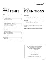
Installation INSTRUCTIONS Professional Series Pro Harmony® Ranges Table of contents (English 2 Table de matières (Français 26 Índice de materias (Español 51 Models | Modèles | Modelos: PRD304WHC/U PRD305WHC/U PRD364WDHC/U PRD364WLHU PRD366WHC/U PRD484WCHU PRD486WDHC/U PRD486WLHU PRG304WH - Thermador PRG304WH | Installation Instructions - Page 4
instructions 3 Installation instructions 6 Planning information 6 Ventilation requirements 6 Installation clearances 7 Gas and electric locations 12 Unpacking and moving the range 13 Installing important information and/or tips. This THERMADOR® appliance is made by BSH Home Appliances Corporation - Thermador PRG304WH | Installation Instructions - Page 5
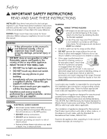
supplier from a neighbor's phone. Follow the gas supplier's instructions. • If you cannot reach your gas supplier, call the fire department. -- Installation and service must be performed by a qualified installer, service agency or the gas supplier. WARNING ELECTRICAL SHOCK HAZARD • Disconnect power - Thermador PRG304WH | Installation Instructions - Page 6
for Household Cooking Gas Appliances • CAN1-1.1-M81, Domestic Gas Ranges • CSA C22.2 No. 61, Household Cooking Ranges Check local building codes for the proper method of appliance installation. Local codes vary; it is the responsibility of the installer to ensure installation is in accordance - Thermador PRG304WH | Installation Instructions - Page 7
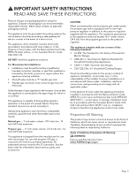
READ AND SAVE THESE INSTRUCTIONS REAR CLEARANCE REQUIREMENTS: • To avoid staining on the back combustible surface*. • When installing against a combustible surface, a Thermador® low backguard is required for a 0'' rear clearance to the combustible surface. A Thermador Low Backguard must be - Thermador PRG304WH | Installation Instructions - Page 8
discolor the back wall under certain cooking conditions. Refer to the "Ventilation Planning Guide" for approved ventilation combinations. It is strongly recommended that this appliance be installed in conjunction with a Thermador® vent hood. Due to the high heat capability of this unit, particular - Thermador PRG304WH | Installation Instructions - Page 9
planning guide" for recommended hood options. Due to the high heat of the burners, installing a microwave oven with a ventilation system over the appliance is not recommended on any model other than the 30'' 5- burner. Refer to OTR manufacturer's installation manual for clearances. • The gas and - Thermador PRG304WH | Installation Instructions - Page 10
152) 3360""(9(71642)) - 18" (457) (76320,"9, 1346,"o, ro1r 24189" ) 5" (127) 35 ⅞" (911) - 36 ¾" (933) inches (mm) as defined in the "National Fuel Gas Code" (ANSI Z223.1, Current Edition). Clearances from non-combustible materials are not part of the ANSI Z21.1 scope and are not certified by - Thermador PRG304WH | Installation Instructions - Page 11
333"0) 0" 3360""(9(71642)) - 18" (457) (76320,"9,1346,"o,ro1r,4281"9 ) 5" (127) 35 ⅞" (911) - 36 ¾" (933) inches (mm) as defined in the "National Fuel Gas Code" (ANSI Z223.1, Current Edition). Clearances from non-combustible materials are not part of the ANSI Z21.1 scope and are not certified - Thermador PRG304WH | Installation Instructions - Page 12
(762) 35 ⅞" (911) - 36 ¾" (933) inches (mm) as defined in the "National Fuel Gas Code" (ANSI Z223.1, Current Edition). Clearances from non-combustible materials are not part of the ANSI Z21.1 scope and surface. • * Refer to OTR manufacturer's installation manual for clearances. Page. 10 - Thermador PRG304WH | Installation Instructions - Page 13
low backguard option is available (purchased separately). • For an island trim install, counter surface should have a cantilever edge meeting the back section of the the rear of the range. • There is a 44-7/8'' (1,140 mm) total clearance. • Shaded area behind range indicates minimum clearance to - Thermador PRG304WH | Installation Instructions - Page 14
high pressure regulator in addition to the pressure regulator supplied with the range. • The gas and electrical supplies must be within the zones as indicated in the image below. • A manual gas shut-off valve must be installed external to the appliance, in a location accessible from the front, for - Thermador PRG304WH | Installation Instructions - Page 15
over brushed-metal surfaces, to protect finish from scratches, until the range is installed in its final position. 3. Remove the grates, burner caps and the front. DO NOT slide the range across an unprotected floor. 4. The range can then be tipped back and supported on the rear legs while the dolly - Thermador PRG304WH | Installation Instructions - Page 16
• A risk of tip-over may exist if the appliance is not installed in accordance with these instructions. For all ranges an anti-tip device MUST be installed. • A child or adult can tip the range and be killed. • DO NOT operate the range without the anti-tip device in place and engaged. Failure to do - Thermador PRG304WH | Installation Instructions - Page 17
gas pipe. Verify the type of gas being used at the installation site. Make certain the range matches the type of gas available at this location. The gas water column (24.9 mb) Gas connection To connect the gas 1. Make sure the gas supply is turned off at the manual shut-off valve before connecting - Thermador PRG304WH | Installation Instructions - Page 18
instructions: • Turn on gas and check supply line connections for leaks using a soap and water solution. • Bubbles forming indicate a gas leak. Repair all leaks immediately. Electrical requirements and connection for GAS models 9 WARNING Before installing, turn power OFF at the service range - Thermador PRG304WH | Installation Instructions - Page 19
been placed in the kick panel area of the range for access by a qualified service technician. • The ranges are to be connected to a 240/208 50 AMPERES DEDICATED CIRCUIT, and marked for use with ranges. It is the responsibility of the installer to provide the proper wiring components (cord, wires, - Thermador PRG304WH | Installation Instructions - Page 20
(UL, CSA, ...) 3-POLE, 3CONDUCTOR cord kit rated 125/250 VOLTS, 50 AMPERES DEDICATED CIRCUIT, and marked for use with ranges. It is the responsibility of the installer to provide the proper wiring components (cord, wires, etc.) and complete the electrical connection as dictated by local codes and - Thermador PRG304WH | Installation Instructions - Page 21
inside the guide channels on the back of the range. 9 WARNING To reduce the risk of fire or injury to persons, check to make sure all packaging has been removed from accessory devices before use. Installation methods will vary upon need. Before you begin read these instructions carefully. Observe - Thermador PRG304WH | Installation Instructions - Page 22
sure the backguard's front face is outside the flange on the front side of the range. 3. Flip the hinge clips for both sides of the door. A screwdriver may be required to carefully pry the clip. 5. Re-install screws removed in Steps 1 and 2. Door removal and adjustment 9 CAUTION • USE CAUTION WHEN - Thermador PRG304WH | Installation Instructions - Page 23
the hinge slots. The hinges will securely hook into the slots when properly installed. DO NOT force, bend or twist the door. If door or handle If the door is properly installed, it should move smoothly and rest straight on the front of the range when closed. 2. The range must be level for proper - Thermador PRG304WH | Installation Instructions - Page 24
rope or twine looped around the gas or electrical supply line as the range is pushed back into its final installed position. Data rating label Data the gas supply have been carefully checked for leaks and that the unit has been connected to the electrical power supply. Turn the manual gas shut- - Thermador PRG304WH | Installation Instructions - Page 25
problems may occur: • Burner flames are too high. • Flames shoot out of burners. • Burners do not ignite. • Burner flames light unevenly. • Burner emits gas odor. Burner grate placement To install If flame characteristics do not improve, call Thermador service. To test burner ignition 1. Select a - Thermador PRG304WH | Installation Instructions - Page 26
. Yellow tips on outer cones: Normal for LP Gas Soft blue flames: Normal for Natural Gas The burners that feature XLO®, cause the flame to port. • There should be no air gap between the flame and burner port. Call Thermador service if: • Any of the burners do not light. • Any of the burners continue - Thermador PRG304WH | Installation Instructions - Page 27
it is certified for use. Manual gas shut off valve installed in an accessible location (without requiring removal of range). Owner is aware of location of the gas shut-off valve. Unit tested and free of gas leaks. If used on propane gas, verify that the propane gas supply is equipped with its own - Thermador PRG304WH | Installation Instructions - Page 28
curit 27 Instructions importants de sécurit 27 Consignes d'installation 30 Renseignements de planification 30 Exigences en matière de ventilation 30 Espaces libres pour l'Installation 31 , ON L5N 7J6 Des questions? 1-800-735-4328 www.thermador.ca Nous attendons de vos nouvelles! Page. 26 - Thermador PRG304WH | Installation Instructions - Page 29
adulte pourrait faire basculer l'appareil et perdre la vie. • Ne faites pas fonctionner l'appareil si le support antibascule n'est pas installé et qu'il ne retient pas l'appareil. La non-observation de ces instructions peut entraîner la mort ou causer de graves brûlures à des enfants ou des adultes - Thermador PRG304WH | Installation Instructions - Page 30
IMPORTANTS DE SÉCURITÉ LIRE TOUTES LES INSTRUCTIONS AVANT DE PROCÉDER L'installation de ces dispositifs conçus pour micro 91,4 centimètres (36"). Vérifiez le type d'alimentation en gaz fourni sur le lieu d'installation. L'appareil doit être raccordé au type de gaz pour lequel il est certifié. Tous - Thermador PRG304WH | Installation Instructions - Page 31
LES INSTRUCTIONS AVANT 152 mm (6 po) d'une surface combustible*. • Lors de l'installation de l'appareil contre une surface combustible, il faut un dosseret bas dégagement (0 po). Il faudrait acheter séparément un dosseret bas Thermador. • Quand une surface est couverte d'une matière non combustible - Thermador PRG304WH | Installation Instructions - Page 32
aux systèmes de ventilation à aspiration ascendante. Consultez le "Guide de planification de ventilation" pour connaître les combinaisons de ventilation approuvées. Il est fortement recommandé d'installer une hotte de ventilation Thermador au-dessus de la cuisinière. Une ventilation par aspiration - Thermador PRG304WH | Installation Instructions - Page 33
-dessus qui doivent comporter un espace assez grand pour recevoir une hotte d'îlot. • Consultez le "Guide de planification de ventilation" pour connaître les combinaisons de ventilation approuvées. L'installation d'un micro-ondes à hotte intégrée au-dessus toute table de cuisson n'est pas recommand - Thermador PRG304WH | Installation Instructions - Page 34
moins 152 mm (6 po) d'une surface combustible*. • Lors de l'installation de l'appareil contre une surface combustible, il faut un dosseret bas pour de dégagement (0 po). Il faudrait acheter séparément un dosseret bas Thermador. • Quand une surface est couverte d'une matière non combustible (métal, - Thermador PRG304WH | Installation Instructions - Page 35
Espace libre - armoires avec garniture d'ilot incluse 1(333"0) 6" (152) 3360""(9(71642)) - 18" (457) (76320,"9, 1346,"o, ro1r 24189" ) 5" (127) 35 ⅞" (911) - 36 ¾" (933) pounces (mm) Les dégagements pour matériaux non-combustibles ne sont pas abordés dans la norme ANSI Z21.1 ni certifiés par - Thermador PRG304WH | Installation Instructions - Page 36
Espace libre - armoires avec dosseret bas (acheter séparément) 1(333"0) 0" 3360""(9(71642)) - 18" (457) (76320,"9,1346,"o,ro1r,4281"9 ) 5" (127) 35 ⅞" (911) - 36 ¾" (933) pounces (mm) Les dégagements pour matériaux non-combustibles ne sont pas abordés dans la norme ANSI Z21.1 ni certifiés - Thermador PRG304WH | Installation Instructions - Page 37
Espaces libres des armoires avec four à micro-ondes installé au-dessus de la cuisinière (seulement 305) 1(333"0) * 30" (762) 18" (457) 5" (127) la surface de cuisson. • * Reportez-vous au manuel d'installation du fabricant du four à micro-ondes pour connaître les espaces libres requis. Page. 35 - Thermador PRG304WH | Installation Instructions - Page 38
) 30" (762) - 36" (914) 36 ¾" (933) - 35 ⅞" (911) 23" (584) 44 ⅞" (1,140) pounces (mm) • Il faudrait acheter séparément un dosseret bas Thermador. • Pour les installations avec garniture d'îlot, une saillie entre le comptoir et la section arrière de la garniture est requise. • Si une paroi int - Thermador PRG304WH | Installation Instructions - Page 39
se trouver dans les zones indiquées. • Un robinet manuel d'arrêt de gaz doit être installé à l'extérieur de l'appareil, à un endroit accessible par le devant, pour pouvoir couper 30", 36", 48" (762, 914, 1219) Gas zone 6" (152) 2" CL (51) Electric zone 6" (152) CL 6" (152) 9" (229) 6" (152 - Thermador PRG304WH | Installation Instructions - Page 40
chauffante, les chapeaux des brûleurs et les grilles du four. 4. Si désiré, vous pouvez également enlever les portes du four (consultez «Retrait et installation de la porte»). 2. Soulevez la cuisinière et retirez-la de la palette. Demandez de l'aide au besoin pour la retirer de la palette. 3. Avec - Thermador PRG304WH | Installation Instructions - Page 41
adulte pourrait faire basculer l'appareil et perdre la vie. • Ne faites pas fonctionner l'appareil si le support antibascule n'est pas installé et qu'il ne retient pas l'appareil. La non-observation de ces instructions peut entraîner la mort ou causer de graves brûlures à des enfants ou des adultes - Thermador PRG304WH | Installation Instructions - Page 42
) de colonne d'eau entre le réservoir de propane et le régulateur à haute pression. Vérifiez le type de gaz utilisé à l'endroit où la cuisinière est installée. Assurez-vous que la cuisinière correspond au type de gaz disponible dans la région. Le branchement à l'arrivée de gaz doit être effectué par - Thermador PRG304WH | Installation Instructions - Page 43
4. Les tests de fuite de l'appareil doivent toujours être réalisés conformément aux instructions du fabricant. • Ouvrez le gaz et assurez-vous qu'il n'y a pas de é au gaz 9 AVERTISSEMENT Avant l'installation, mettre l'alimentation HORS CIRCUIT au panneau de service, le verrouiller pour empêcher la - Thermador PRG304WH | Installation Instructions - Page 44
des risques d'électrocution. 9 AVERTISSEMENT Cet appareil électroménager doit être mis à la terre. • Avant l'installation, couper l'alimentation au panneau de service. Verrouiller le panneau de service pour empêcher que l'alimentation ne soit rétablie par accident. • Avant d'effectuer l'entretien de - Thermador PRG304WH | Installation Instructions - Page 45
se touchent pas. 8. Serrez bien toutes les connexions. 9. Réinstallez le couvercle du bloc de jonction. Connexion à trois fils Cet appareil prêt-à-installer est fabriqué avec un cordon d'alimentation à quatre fils et une prise. Toutefois, lorsque les normes et codes locaux permettent une mise à la - Thermador PRG304WH | Installation Instructions - Page 46
du dosseret 9 AVERTISSEMENT Vous pourriez vous pincer les doigts ou les mains et vous blesser gravement lors de l'installation de cet accessoire. Soyez très prudent et portez des gants protecteurs épais pour éviter toute coupure ou lacération des doigts ou des mains lorsque - Thermador PRG304WH | Installation Instructions - Page 47
l'avant de la cuisinière. 4. Assurez-vous que la face du dosseret est à l'extérieur des brides, vers l'avant de la cuisinière. Retrait et installation de la porte 9 MISE EN GARDE • FAITES ATTENTION LORSQUE VOUS ENLEVEZ LA PORTE. ELLE EST TRÈS LOURDE. • Pour éviter tout risque de brûlure ou - Thermador PRG304WH | Installation Instructions - Page 48
'elle bouge normalement et qu'elle s'adapte bien à la cavité du four. Ne forcez pas pour l'ouvrir ou la fermer. Si la porte est bien installée, elle devrait être facile à ouvrir et être alignée avec le devant du four lorsqu'elle est en position fermée. 2. La cuisinière doit être bien - Thermador PRG304WH | Installation Instructions - Page 49
au niveau 3. Vous devez ajuster totalement les deux pattes arrière avant de pousser la cuisinière à son emplacement définitif. • Au moment d'installer la cuisinière à son emplacement définitif, assurez-vous que le dispositif anti-bascule s'insère correctement. Pour ce faire, vous pouvez regarder - Thermador PRG304WH | Installation Instructions - Page 50
de la base ne doivent pas être enlevés sauf par un technicien de service. Remettez en place après l'entretien. Test de brûleurs 9 AVERTISSEMENT Pour chauds. Éteignez la table de cuisson et laissez les brûleurs refroidir. Installer tout composant lâche, tels capuchons et grilles de brûleurs, ayant - Thermador PRG304WH | Installation Instructions - Page 51
les regardez d'en haut. Positionnement des grilles des brûleurs Pour installer les grilles des brûleurs 1. Positionnez-les avec le côté plat Si les caractéristiques de flamme ne s'améliorent pas, communiquer avec Thermador entretien. Vérifier l'allumage de brûleur 1. Choisir un bouton de surface - Thermador PRG304WH | Installation Instructions - Page 52
retiré. La garniture d'îlot ou le dosseret installé selon les instructions. Lorsque le sélecteur est réglé Conditioner de Thermador, en vente à la boutique électronique Thermador (www.thermador.com/customer- reporter au Guide d'utilisation et d'entretien. Dépannage Voyez le Guide d'Utilisation et - Thermador PRG304WH | Installation Instructions - Page 53
(necesaria 64 Requerimientos de gas y conexiones 65 Requerimientos eléctricos y conexión para unidades de gas 66 Mixtas conexión elé sobre información y/o consejos importantes. Página. 51 Este electrodoméstico de THERMADOR® está hecho por BSH Home Appliances Corporation 1901 Main Street, Suite - Thermador PRG304WH | Installation Instructions - Page 54
cerca de este o cualquier otro aparato. -- QUÉ HACER CUANDO HUELE A GAS • No trate de encender ningún aparato. • No toque ningún interruptor el no retiene el aparato. • El hecho de no leer las instrucciones de este manual puede causar la muerte o graves quemaduras a niños y adultos. • Cuando - Thermador PRG304WH | Installation Instructions - Page 55
digo Eléctrico de Canadá (CSA C22.1-02). NO instale esta estufa afuera. Para Instalaciones en Massachusetts 1. La instalación debe realizarse por un Este electrodoméstico viene configurado de fábrica para usarlo con gas natural. Para usarlo con gas propano (LP), se debe comprar por separado un kit de - Thermador PRG304WH | Installation Instructions - Page 56
1-B149.1 and .2 - Installation Codes for Gas Burning Appliances (Códigos de Instalación para Unidades que Queman Gas) y/o códigos locales. Requisitos Se debe comprar por separado una consola trasera de protección baja de Thermador. • Una separación trasera respecto a una superficie cubierta con un - Thermador PRG304WH | Installation Instructions - Page 57
capacidades de las campanas que se recomiendan usar con todas las estufas Thermador. Debido al alto calor de los quemadores de la placa de cocci nada que no sea la placa de 5 quemadores de 30". Consulte el manual de instalación del fabricante OTR para obtener información sobre los espacios que deben - Thermador PRG304WH | Installation Instructions - Page 58
cocción ni tampoco nada que no sea la placa de 5 quemadores de 30". Consulte el manual de instalación del fabricante OTR para obtener información sobre los espacios que deben quedar libres. • El suministro de gas y la alimentación eléctrica deben estar dentro de la zona indicada en la "Ubicación de - Thermador PRG304WH | Installation Instructions - Page 59
152 mm) respecto a una superficie combustible*. • Cuando se instale sobre una superficie combustible, se requiere una consola trasera de protecci Se debe comprar por separado una consola trasera de protección baja de Thermador. • Una separación trasera respecto a una superficie cubierta con un - Thermador PRG304WH | Installation Instructions - Page 60
Espacios libres con la adorno tipo isla incluida 1(333"0) 6" (152) 3360""(9(71642)) - 18" (457) (76320,"9, 1346,"o, ro1r 24189" ) 5" (127) 35 ⅞" (911) - 36 ¾" (933) pulg. (mm) Las separaciones de materiales no combustibles no son parte del alcance ANSI Z21.1 y no están certificadas por CSA. - Thermador PRG304WH | Installation Instructions - Page 61
Espacios libres con la consola trasera baja 1(333"0) 0" 3360""(9(71642)) - 18" (457) (76320,"9,1346,"o,ro1r,4281"9 ) 5" (127) 35 ⅞" (911) - 36 ¾" (933) pulg. (mm) Las separaciones de materiales no combustibles no son parte del alcance ANSI Z21.1 y no están certificadas por CSA. *Las - Thermador PRG304WH | Installation Instructions - Page 62
los códigos locales y/o por la autoridad local competente. • 30 pulg. (762 mm) min. parte inferior de la campana y la superficie de la estufa. • Consulte el manual de instalación del microondas para conocer los espacios libres requeridos. Página. 60 - Thermador PRG304WH | Installation Instructions - Page 63
Espacio libre en pared lateral 6" (152) 28" (711) 30" (762) - 36" (914) 24 ⅝" (625) 23 ⅞" (606) 24 ¾" (629) 36 ¾" (933) - 35 ⅞" (911) 23" (584) 44 ⅞" (1,140) pulg. (mm) • El modelo que se muestra es con adorno tipo isla incluido. Una opción de consola trasera baja está disponible (se compra - Thermador PRG304WH | Installation Instructions - Page 64
Ubicación de los eléctricos y de gas Requisitos de gas y electricidad • IMPORTANTE: Si aún no existe, instale una válvula manual de cierre de gas en un lugar de fácil acceso. Asegúrese de que todos los usuarios sepan dónde y cómo cerrar el suministro de gas de la estufa. • Se debe usar una línea - Thermador PRG304WH | Installation Instructions - Page 65
ocultas del aparato pueden tener salientes cortantes. Tenga cuidado al sujetar el aparato por debajo o por atrás. No use una carretilla de manutención manual o un carro para electrodoméstico en las partes frontal o trasera del aparato. Úselos únicamente en los lados. Desempacar la estufa NOTA: • Una - Thermador PRG304WH | Installation Instructions - Page 66
No utilice el aparato si el dispositivo antivuelco no está instalado y no retiene el aparato. • El hecho de no leer las instrucciones de este manual puede causar la muerte o graves quemaduras a niños y adultos. • Cuando jale la estufa de la pared por motivos de limpieza, servicio u otra razón, aseg - Thermador PRG304WH | Installation Instructions - Page 67
debe estar aislado del sistema de tubería de suministro de gas cerrando la válvula manual de cierre durante cualquier prueba de la línea de suministro de gas a presiones de prueba igual a o inferior a ½ psi (3,5kPa.). Verifique el tipo de gas que se está usando en el lugar de instalación. Aseg - Thermador PRG304WH | Installation Instructions - Page 68
de no aplicar demasiada presión al apretar las juntas. 4. Las pruebas de fugas del aparato deben estar conforme a las siguientes instrucciones. • Prenda el gas y revise las conexiones de la línea desuministro para ver si hay fugas usando una solución con agua y jabón. • Burbujas que aparecen indican - Thermador PRG304WH | Installation Instructions - Page 69
• Observe todos los códigos y regulaciones durante la puesta a tierra. A falta de estos códigos y regulaciones, observe el Código Eléctrico Nacional ANSI/NFPA No. 70 edición actual. • El cable de alimentación no debe salir más de 2 pulg. 2" (51 mm) de la pared trasera. (51) NOTA: El tipo de - Thermador PRG304WH | Installation Instructions - Page 70
tuercas superiores solamente de los bornes de la caja de conexiones. No quite las tuercas inferiores que fijan los cables del cableado interno a la estufa. 3. Instale el prensacables (no incluido con la estufa) en el orificio de 1 pulg. (6 mm) de diámetro situado en el panel trasero, debajo de la - Thermador PRG304WH | Installation Instructions - Page 71
2. Instale el prensacables (no incluido con la estufa) en el orificio de 1 pulg. (6 mm) de diámetro situado en el panel trasero, debajo de la caja - Thermador PRG304WH | Installation Instructions - Page 72
4. Cierre la puerta despacio hasta apoyarla contra los soportes de las bisagras. Cuando ésas están en posición abierta, la puerta se queda abierta a un ángulo de unos 30° respecto a su posición cerrada. 5. Agarre la puerta de los extremos y levántela. Los resortes ofrecerán un poco de resistencia. - Thermador PRG304WH | Installation Instructions - Page 73
Instalación de la consola trasera 9 ADVERTENCIA Tenga cuidado para no pellizcarse les dedos o las manos al instalar la consola trasera. Podría lesionarse gravemente. Lleve guantes de protección gruesos para evitar cortarse o lastimarse los dedos o las manos al deslizar la consola sobre la estufa. - Thermador PRG304WH | Installation Instructions - Page 74
y los cables eléctricos según va empujando la estufa hacia su posición final. Para conseguirlo, le sugerimos jalar cuidadosamente el suministro de gas y el cable eléctrico con una cuerda o un cordel mientras empuja la estufa hacia su posición final. Ajuste del rodapié 1. Coloque el rodapié en una - Thermador PRG304WH | Installation Instructions - Page 75
saber si hay fugas y que la unidad haya sido conectada con la fuente de la corriente eléctrica. Dar vuelta a la válvula de cierre manual del gas a la posición abierta. Para asegurar un funcionamiento correcto, se deben colocar correctamente las tapas de los quemadores STAR® sobre su base. Si la tapa - Thermador PRG304WH | Installation Instructions - Page 76
de los quemadores no queda completamente envuelto, llame al Servicio de Thermador mantenimiento. 3. Repita los procedimientos de prueba de Encendido y Flama más ajuste. Puntas amarillas sobre conos: Normal para Gas LP. Flama azul suave: Normal para Gas Natural. Si la flama es casi o completamente - Thermador PRG304WH | Installation Instructions - Page 77
á conectado solamente al tipo de gas para el cual está certificado. Se instaló la válvula de cierre manual de gas en un lugar accesible (sin Thermador, disponible en la tienda en línea de Thermador (www.thermador.com/customer-care). • Para decoloraciones o suciedades persistentes, consulte el manual - Thermador PRG304WH | Installation Instructions - Page 78
- Thermador PRG304WH | Installation Instructions - Page 79
- Thermador PRG304WH | Installation Instructions - Page 80
to help you with cleaning and care instructions, cooking tips, accessories, troubleshooting, and more. USA: 1-800-735-4328 thermador.com/customer-care Canada: 1-800-735-4328 thermador.ca/support Accessories and parts Filters, Thermador cleaners, teppanyaki pans, griddles, replacement parts, and
-
 1
1 -
 2
2 -
 3
3 -
 4
4 -
 5
5 -
 6
6 -
 7
7 -
8
-
9
-
10
-
11
-
12
-
13
-
14
-
15
-
16
-
17
-
18
-
19
-
20
-
21
-
22
-
23
-
24
-
25
-
26
-
27
-
28
-
29
-
30
-
31
-
32
-
33
-
34
-
35
-
36
-
37
-
38
-
39
-
40
-
41
-
42
-
43
-
44
-
45
-
46
-
47
-
48
-
49
-
50
-
51
-
52
-
53
-
54
-
55
-
56
-
57
-
58
-
59
-
60
-
61
-
62
-
63
-
64
-
65
-
66
-
67
-
68
-
69
-
70
-
71
-
72
-
73
-
74
-
75
-
76
-
77
-
78
-
79
-
80
 |
 |

THERMADOR.COM
Installation
INSTRUCTIONS
Professional Series Pro Harmony
®
Ranges