Viking VGRT244TNSS Installation Instructions
Viking VGRT244TNSS Manual
 |
View all Viking VGRT244TNSS manuals
Add to My Manuals
Save this manual to your list of manuals |
Viking VGRT244TNSS manual content summary:
- Viking VGRT244TNSS | Installation Instructions - Page 1
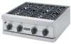
Viking Installation Guide Viking Range Corporation 111 Front Street Greenwood, Mississippi 38930 USA (662) 455-1200 For product information, call 1-888-VIKING1 (845-4641) or visit the Viking Web site at vikingrange.com F20056I EN (033108J) VGSB T-Series Outdoor 15" Wide Double Side Burners & VGRT - Viking VGRT244TNSS | Installation Instructions - Page 2
in accordance with the manufacturer's instructions, this product could expose you -1 connection or standard residential 1/2" (1.3 cm) ID gas service line. Side Burner Rating (2) - 15,000 BTU Nat supply piping system by closing its individual manual shut-off valve during any pressure testing - Viking VGRT244TNSS | Installation Instructions - Page 3
Assembly Installer supplied flexible gas line with 1/2" female flare adaptor or Viking GHS12 LP/PROPANE FIXED PIPING CONNECTION Connection: Operating Pressure: Supply Pressure: Standard Residential 1/2" ID gas service line - 1/2" NPT male with 3/8" flare adapter. 10.0" W.C.P. Nat. 11" to 14 - Viking VGRT244TNSS | Installation Instructions - Page 4
MUST be some type of support (braces, cut-out, etc.) to prevent tank from moving within the installation. The support must also allow the LP/ valve. Remove the cylinder from the grill. Call an authorized gas appliance service technician or LP/Propane gas dealer. Do not use the grill until the - Viking VGRT244TNSS | Installation Instructions - Page 5
a built-in construction where an LP/Propane tank is going to be used, there MUST be some type of support (braces, cutout, etc.) to prevent tank from moving within the installation. The support must also allow the LP/Propane tank to withstand a horizontal tipping force equal to the weight of the tank - Viking VGRT244TNSS | Installation Instructions - Page 6
Built-In Clearance Dimensions Side View 10 VENTILATION FOR BUILT-IN INSTALLATIONS Not less than 5.00 inches from inside bottom of countertop. Vents 5.00 inch maximum No more than 5.00 inches above the floor of the installation. 5.00 inch maximum 1.00 inch maximum Not less than 1.00 inch from - Viking VGRT244TNSS | Installation Instructions - Page 7
burners, remove the grates, burner bowls, and grate support. With a screw driver, loosen the lock-screw regulator connected and set. 4. Manual shut-off valve installed and of the installer not following instructions will be responsibility of the be used in performing service on the side burners. Do - Viking VGRT244TNSS | Installation Instructions - Page 8
14 15
-
 1
1 -
 2
2 -
 3
3 -
 4
4 -
 5
5 -
 6
6 -
 7
7 -
8
 |
 |

Viking Range Corporation
111 Front Street
Greenwood, Mississippi 38930 USA
(662) 455-1200
For product information,
call 1-888-VIKING1 (845-4641)
or visit the Viking Web site at
vikingrange.com
F20056I EN
(033108J)
Viking Installation Guide
VGSB T-Series Outdoor 15” Wide Double Side
Burners & VGRT 24” Wide Outdoor Rangetop