Viking VIPR161RSS Installation Instructions
Viking VIPR161RSS Manual
 |
View all Viking VIPR161RSS manuals
Add to My Manuals
Save this manual to your list of manuals |
Viking VIPR161RSS manual content summary:
- Viking VIPR161RSS | Installation Instructions - Page 1
, keep drywall spray, construction dust, etc. off power unit. 3. Clean filters and grease-laden surfaces frequently. 4. Do not repair or replace any part of this appliance unless specifically recommended in this manual. All other servicing should be done by a qualified technician. 5. Please read - Viking VIPR161RSS | Installation Instructions - Page 2
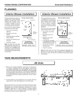
to the cooktop installation instructions for dimensions of cooktop, countertop cut-out, and cabinet requirements. The Models VIPR102SS and VIPR102RSS will fit in most 30" wide cabinets the Models VIPR162SS and VIPR162RSS will fit in most 36" wide cabinets and the Models VIPR182SS and VIPR182RSS - Viking VIPR161RSS | Installation Instructions - Page 3
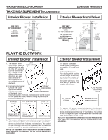
VIKING RANGE CORPORATION TAKE MEASUREMENTS (CONTINUED) Downdraft Ventilators Interior Blower Installation SIDE VIEW OF DOWNDRAFT WITH VIDV500 INTERIOR BLOWER 2" 7 11 16 " 1" 3 1 4 " 3 5 8 " 18" 5" VVIIDV550000 ININTTEERRNIOARL BBLLOOWWEERR 1" 4 2 1 8 " 29 5 16 " FROM - Viking VIPR161RSS | Installation Instructions - Page 4
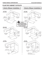
VIKING RANGE CORPORATION PLAN THE CABINET CUTOUTS Interior Blower Installation Downdraft Ventilators Exterior Blower Installation LEFT SIDE DISCHARGE LEFT SIDE DISCHARGE CENTER LINES OF DUCT CUTOUT 10¼" x 3½" CUTOUT (TYP.) RIGHT SIDE DISCHARGE 241/8" 5½" CENTER LINE OF COUNTER CUTOUT CENTER - Viking VIPR161RSS | Installation Instructions - Page 5
30" wide cabinet... or Models VIPR162SS or VIPR162RSS are being installed in a 36" wide cabinet... or Models VIPR182SS or VIPR182RSS are being installed in a 48" wide cabinet... ...the outlet cannot be located on the back wall of cabinet. In these cases, the width of the downdraft covers nearly the - Viking VIPR161RSS | Installation Instructions - Page 6
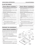
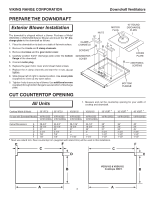
VIKING RANGE CORPORATION Downdraft Ventilators PREPARE THE DOWNDRAFT Exterior Blower Installation The downdraft is shipped without a blower. Purchase a Model VEDV900 or VEDV1200 Exterior Blower and mount the 10" discharge plate to the downdraft as follows: 1. Place the downdraft on its back on a - Viking VIPR161RSS | Installation Instructions - Page 7
is provided for installers who prefer to rivet the ductwork to the unit.This will allow blower to be removed and replaced easily in service situations without disturbing air tight. 3. Connect ductwork to downdraft. If necessary, LOOSEN nuts and screws that hold remote blower adapter plate in place, - Viking VIPR161RSS | Installation Instructions - Page 8
or bare wire. 6. Replace wiring box cover. 7. Plug the downdraft's power cord into outlet. Make sure that the power cord is routed away from the heat generated by the cooktop. "R" MODEL DOWNDRAFT REFSILETTER 1234 N UP/DOW TO RANGETOP REMOTE CONTROL MIN. FILTER 123 DOWUNP 4 COUNTERTOP - Viking VIPR161RSS | Installation Instructions - Page 9
VIKING RANGE CORPORATION Downdraft Ventilators INSTALLATION OF REMOTE CONTROL SWITCH WARNING: To reduce the risk of burns or ignition of clothing by reaching across burners, the remote control must be mounted at least 4" away from any cook top burner. Keep in mind you do not want to place the - Viking VIPR161RSS | Installation Instructions - Page 10
VIKING RANGE CORPORATION Downdraft Ventilators This page has been left blank intentionally. BACKSIDE OF REMOTE SWITCH TEMPLATE 10 - Viking VIPR161RSS | Installation Instructions - Page 11
ON after 30 hours of operation to remind you to clean filters. Press button to reset. REFSILETTER 1234 USE AND CARE FILTER UP DOWN 1234 U P/D O W N TOP COVER CONTROL FOR MODELS VIPR102SS VIPR162SS VIPR182SS Always turn the downdraft blower on before you begin cooking to All Units Wash - Viking VIPR161RSS | Installation Instructions - Page 12
part or parts. Replacement of a component part includes its free installation. Warrantor's liability on any claim of any kind, with respect to the goods or services covered hereunder, shall in no case exceed the price of the goods or service or part there of which gives rise to the claim. WARRANTY - Viking VIPR161RSS | Installation Instructions - Page 13
10 cm (4 po) des brûleurs de la cuisinière. Consultez les instructions à la page 20 "INSTALLATION DE LA SURFACE DE CUISSON". LIRE ET CONSERVER CES INSTRUCTIONS ! DESTINÉ À LA CUISINE DOMESTIQUE SEULEMENT ! AVERTISSEMENT AVERTISSEMENT AFIN DE DIMINUER LES RISQUES D'INCENDIE, D'ÉLECTROCUTION - Viking VIPR161RSS | Installation Instructions - Page 14
VIKING RANGE CORPORATION PRÉPARATION VeDnotwilantderuarfst Veennctaislatrtoésrs Installation du ventilateur intérieur Ce ventilateur encastré est conçu pour évacuer les contaminants INSTALLATION appareils 1. Consultez les instructions d'installation pour connaître les 91,4 cm (36 po) de largeur - Viking VIPR161RSS | Installation Instructions - Page 15
VIKING RANGE CORPORATION PRISE DES MESURES (SUITE) Installation du ventilateur intérieur VUE DE CÔTÉ DE LA HOTTE AVEC VENTILATEUR INTÉRIEUR VIDV500 BOTTOM OF AIR BOX PRÉPARATION DES CONDUITS VeDnotiwlantdeurarfst eVnencatislatrtéosrs Installation du ventilateur extérieur 5 cm (2 po) 2" VUE DE - Viking VIPR161RSS | Installation Instructions - Page 16
VIKING RANGE CORPORATION VeDnotwilantdeurarfst eVnencatislatrtéosrs PRÉPARATION DU DÉCOUPAGE DE L'ARMOIRE Installation du ventilateur intérieur Installation du ventilateur extérieur SORTIE À GAUCHE SORTIE À GAUCHE LIGNES DE CENTRE DU CDEÉNCTOEURPAGLEINPEOSUORF DCUOCNTDCUUITTOUT TRO10U¼("TxYP3 - Viking VIPR161RSS | Installation Instructions - Page 17
VIPR162SS ou VIPR162RSS sont installés dans une armoire de 91,4 cm (36 po) de largeur... ou les modèles VIPR182SS ou VIPR182RSS sont installés dans une armoire de fourni et être reliés à la prise de downdraft (incluse). PRÉPARATION DE LA HOTTE Installation du ventilateur intérieur SORTIE DE 8,3 x - Viking VIPR161RSS | Installation Instructions - Page 18
VIKING RANGE CORPORATION VeDnotiwlantedurarsft eVnecnatislatrtéosrs PRÉPARATION DE LA HOTTE Installation du cm (30 po) 61 cm (24po) 68,6 cm (27po) 7 cm (2¾ po) 3,8 cm (1½ po) 3,8 cm (1½ po) 91,4 cm (36 po) 61 cm (24po) 83,8 cm (33po) 7 cm (2¾ po) 3,8 cm (1½ po) 3,8 cm (1½ po) 121,1 cm (48 po) - Viking VIPR161RSS | Installation Instructions - Page 19
VIKING RANGE CORPORATION VeDnotwilantderuarfst Veennctaislatrtoésrs INSTALLATION DE L'UNITÉ Tous les modèles 1. Placez la hotte dans l'ouverture.Allongez les brides de nivellement jusqu'au plancher de l'armoire afin que la hotte s' - Viking VIPR161RSS | Installation Instructions - Page 20
VIKING RANGE CORPORATION CÂBLAGE ÉLECTRIQUE Installation du ventilateur intérieur ! ATTENTION : Le câblage UP/DOW (1/11,66 (1à/03,28TpmOom) mm po) CUISINIÈRE TÉLÉCOM- (410poc)mMANDE MIN. FILTER 123 DOWUNP 4 COMPTOIR Note: Remarque : La cuisinière et la surface de cuisson de conception - Viking VIPR161RSS | Installation Instructions - Page 21
VIKING RANGE CORPORATION VeDnotwilantderuarfst Veennctaislatrtoésrs INSTALLATION DE LA TÉLÉCOMMANDE AVERTISSEMENT : Pour réduire les risques de brûlure ou que des vêtements s'enflamment en traversant les brûleurs, la télécommande doit être installée à au moins 10 cm (4 po) des brûleurs de la - Viking VIPR161RSS | Installation Instructions - Page 22
VIKING RANGE CORPORATION VeDnotiwlantdeurarfst eVnencatislatrtéosrs Cette page a été laissée en blanc volontairement. ARRIÈRE DU GABARIT DE LA TÉLÉCOMMANDE 22 - Viking VIPR161RSS | Installation Instructions - Page 23
VIKING RANGE CORPORATION VeDnotwilantderuarfst Veennctaislatrtoésrs FONCTIONNEMENT HAUT/BAS ---R e l è VIPR102SS, VIPR162SS et VIPR182SS est situé à droite de la VIPR162RSS télécommande. VIPR182RSS FILTER DÉLAI Actionne le ventilateur pendant 10 minutes une fois que l'on a appuyé sur - Viking VIPR161RSS | Installation Instructions - Page 24
installation. La responsabilité du garant, quelle que soit la réclamation relative aux biens ou aux services couverts par la présente, ne saurait dépasser le prix des biens, services produit, une agence de réparation agréée de Viking Range Corporation ou Viking Range Corporation. Précisez le modèle - Viking VIPR161RSS | Installation Instructions - Page 25
VIKING RANGE CORPORATION Ventiladores de tiro descendente MODELO VIPR102 VIPR102R VIPR162 VIPR162R VIPR182 VIPR182R ANCHO 30 pulg. (76.2 cm) 30 pulg. (76.2 cm) c/control remoto 36 pulg. (91.4 cm) 36 . Consulte la sección "INSTALE LA ESTUFA" en la . INSTALADOR: Conserve este manual para que lo use - Viking VIPR161RSS | Installation Instructions - Page 26
VIKING y el sistema eléctrico. • Instale la estufa. INSTALACIÓN TÍPICA SUPERFICIE DEL GABINETE PARTE SUPERIOR DE LA CHIMENEA ESTUFA CUBIERTA ; los modelos VIPR162SS y VIPR162RSS ajustarán en la mayoría de los gabinetes de 36 pulg. (90 cm) de ancho, y los modelos VIPR182SS y VIPR182RSS ajustarán - Viking VIPR161RSS | Installation Instructions - Page 27
VIKING RANGE CORPORATION TOME MEDIDAS (CONTINUACIÓN) Instalación del ventilador 3/16 pulg. (8.1 cm) CODO REDONDO DE 10 pulg. (25 cm) 29 5/16 pulg. (74.4 cm) LA PARTE SUPERIOR DEL GABINETE HASTA LA PARTE INFERIOR DE LA CAJA DE AIRE 13 1/4 pulg. (33.66 cm) PLANEE LOS CONDUCTOS 1 9/16 pulg. (3.97 - Viking VIPR161RSS | Installation Instructions - Page 28
VIKING RANGE CORPORATION Ventiladores de tiro descendente PLANEE LOS CORTES DEL GABINETE Instalación del ventilador interior Instalación del ventilador exterior DESCARGA DEL LADO IZQUIERDA LÍNEAS CENTRALES - Viking VIPR161RSS | Installation Instructions - Page 29
VIKING ancho... o si los modelos VIPR162SS o VIPR162RSS se van a instalar en un gabinete de 36 pulg. (90 cm) de ancho... o si los modelos VIPR182SS o VIPR182RSS se van descendente, como sigue: 1. Coloque el tiro descendente sobre su parte posterior en una mesa o una superficie de trabajo plana. 2. - Viking VIPR161RSS | Installation Instructions - Page 30
VIKING ) al tiro descendente tal como sigue: 1. Coloque el tiro descendente sobre su parte posterior en una mesa o una superficie de trabajo plana. 2. Quite las . VGSU162 VGRT de VGRT de VGRT de 30 pulg. (75 cm)* 36 pulg. (90 cm)* 48 pulg. (120 cm)* VIPR162SS VIPR162RSS VIPR102RSS VIPR162RSS - Viking VIPR161RSS | Installation Instructions - Page 31
VIKING RANGE CORPORATION Ventiladores de tiro parte inferior del gabinete. Apriete los tornillos que fijan los soportes de nivelación a la unidad en cada lado. TORNILLOS DE MONTAJE SOPORTE DE NIVELACIÓN, REBORDE ORIENTADO HACIA AFUERA SOPORTE DE NIVELACIÓN, REBORDE ORIENTADO HACIA ADENTRO INSTALE - Viking VIPR161RSS | Installation Instructions - Page 32
VIKING RANGE CORPORATION Ventiladores de tiro descendente INSTALE EL CABLEADO ELÉCTRICO Instalación del parte frontal de la cubierta del tiro descendente. TIRO DESCENDENTE MODELO "R" REFSILETTER 1234 N UP/DOW 0.01(60/1.c061m3/p3)Tau2Olga. ESTUFA CONTROL 4 (10 REMOTO cpmul)g. mín. FILTER - Viking VIPR161RSS | Installation Instructions - Page 33
VIKING RANGE CORPORATION Ventiladores de tiro descendente INSTALACIÓN DEL INTERRUPTOR DEL en la unidad del tiro descendente. (El orificio del receptáculo para el gabinete se encuentra en la parte inferior derecha del tiro descendente.) 6. Acomode el exceso de cable donde no estorbe y fije el cable - Viking VIPR161RSS | Installation Instructions - Page 34
VIKING RANGE CORPORATION Ventiladores de tiro descendente Esta página se ha dejado en blanco intencionalmente. PARTE POSTERIOR DE LA PLANTILLA DEL CONMUTADOR REMOTO 34 - Viking VIPR161RSS | Installation Instructions - Page 35
VIKING RANGE recordarle cambiar los filtros. Oprima el botón para reiniciar. FILTER UP DOWN 1234 U P/D O W N CUBIERTA SUPERIOR PARA Así mantendrá toda la cocina lengüeta que se encuentra en la parte ADVERTENCIA: Siempre desconecte el suministro eléctrico superior de cada filtro. antes - Viking VIPR161RSS | Installation Instructions - Page 36
, en ningún caso excederá el precio de los productos o servicio o parte del mismo que dé origen al reclamo. SERVICIO BAJO LA GARANTÍA: Según compró el producto, con un agente de servicio autorizado por Viking Range Corporation o con Viking Range Corporation. Proporcione el modelo y el número de
-
 1
1 -
 2
2 -
 3
3 -
 4
4 -
 5
5 -
 6
6 -
 7
7 -
8
-
9
-
10
-
11
-
12
-
13
-
14
-
15
-
16
-
17
-
18
-
19
-
20
-
21
-
22
-
23
-
24
-
25
-
26
-
27
-
28
-
29
-
30
-
31
-
32
-
33
-
34
-
35
-
36
 |
 |

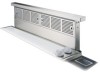
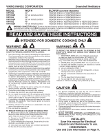
VIKING RANGE CORPORATION
Downdraft Ventilators
WARNING
READ AND SAVE THESE INSTRUCTIONS
WARNING
TO REDUCE THE RISK OF FIRE, ELECTRIC SHOCK, OR
INJURY TO PERSONS, OBSERVE THE FOLLOWING:
1.
Use this unit only in the manner intended by the manufacturer.
If you have questions, contact the manufacturer at the address
or telephone number in the warranty.
2.
Before servicing or cleaning unit, switch power off at service panel
and lock the service disconnecting means to prevent power from
being switched on accidentally.When the service disconnecting
means cannot be locked, securely fasten a prominent warning
device, such as a tag, to the service panel.
3.
Installation work and electrical wiring must be done by a qualified
person(s) in accordance with all applicable codes and standards,
including fire-rated construction codes and
standards.
4.
Sufficient air is needed for proper combustion and exhausting
of gases through the flue (chimney) of fuel burning equipment
to prevent backdrafting. Follow the heating equipment
manufacturer’s guideline and safety standards such as those
published by the National Fire Protection Association (NFPA),
and the American Society for Heating, Refrigeration and
Air Conditioning Engineers (ASHRAE), and the local code
authorities.
5. When cutting or drilling into wall or ceiling, do not damage
electrical wiring and other hidden utilities.
6. Ducted fans must always be vented to the outdoors.
7.
To reduce the risk of fire, use only metal ductwork.
8. Do not install this product with the activating switch directly
behind a burner or element. Minimum distance between the
switch and the edge of the burner should be 4 inches.
9.
Loose-fitting or hanging clothing should never be worn when
operating this appliance. They may be ignited by burners/
elements on cooktop.
10. Children should not be left alone or unattended in the area
where this appliance is in use.
11. This unit must be grounded.
TO REDUCE THE RISK OF A RANGE TOP GREASE FIRE:
a) Never leave surface units unattended at high settings.
Boilovers cause smoking and greasy spillovers that may
ignite. Heat oils slowly on low or medium settings.
b) Always turn hood ON when cooking at high heat or when
cooking flaming foods.
c) Clean ventilating fans frequently. Grease should not be
allowed to accumulate on fan or filter.
d) Use proper pan size. Always use cookware appropriate
for the size of the surface element.
TO REDUCE THE RISK OF INJURY TO PERSONS IN THE
EVENT OF A RANGE TOP GREASE FIRE, OBSERVE THE
FOLLOWING
a
:
1.
SMOTHER FLAMES with a close-fitting lid, cookie sheet,
or metal tray, then turn off the burner. BE CAREFUL TO
PREVENT BURNS. If the flames do not go out immedi
ately, EVACUATE AND CALL THE FIRE DEPARTMENT.
2.
NEVER PICK UP A FLAMING PAN - You may be burned.
3. DO NOT USE WATER, including wet dishcloths or towels
- a violent steam explosion will result.
4. Use an extinguisher ONLY if:
A. You know you have a Class ABC extinguisher, and you
already know how to operate it.
B. The fire is small and contained in the area where it
started.
C. The fire department is being called.
D. You can fight the fire with your back to an exit.
a
Based on “Kitchen Firesafety Tips” published by NFPA.
MODEL
WIDTH
BLOWER
(purchase separately)
VIPR102
30"
VIDV500 Interior or VEDV900 Exterior
VIPR102R
30" w/ remote control
VIDV500 Interior or VEDV900 Exterior
VIPR162
36"
VIDV500 Interior or VEDV900 Exterior
VIPR162R
36" w/ remote control
VIDV500 Interior or VEDV900 Exterior
VIPR182
48"
VIDV500 Interior, VEDV900 Exterior or VEDV1200 Exterior
VIPR182R
48" w/ remote control
VIDV500 Interior, VEDV900 Exterior or VEDV1200 Exterior
WARNING - RANGETOPS ONLY:
To reduce the risk of burns or ignition of clothing by reaching across burners, an "R" model
downdraft (with remote control)
MUST
be used with a rangetop. The remote control
MUST
be mounted in the countertop - at least
4" from the burners. See "INSTALL COOKTOP" section on page 8.
!
INSTALLER:
Save this manual for Electrical
Inspector and Homeowner to use.
HOMEOWNER:
Use and Care Information on Page 11.
CAUTION
1. For general ventilating use only. Do not use to exhaust
hazardous or explosive materials and vapors.
2.
To avoid motor bearing damage and noisy and/or unbalanced
impellers, keep drywall spray, construction dust, etc. off power
unit.
3. Clean filters and grease-laden surfaces frequently.
4. Do not repair or replace any part of this appliance unless
specifically recommended in this manual. All other servicing
should be done by a qualified technician.
5.
Please read specification label on product for further information
and requirements.
6.
DO NOT INSTALL WITH GRILL MODEL RANGETOPS. This
will void the warranty.
7.
Models VIPR102SS, VIPR162SS, and VIPR182SS (non-
remote units):
DO NOT INSTALL WITH RANGETOPS. This
will void the warranty.
!
INTENDED FOR DOMESTIC COOKING ONLY
!