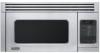
Viking VMOR205SS Installation Instructions
Viking VMOR205SS Manual
 |
View all Viking VMOR205SS manuals
Add to My Manuals
Save this manual to your list of manuals |
Viking VMOR205SS manual content summary:
- Viking VMOR205SS | Installation Instructions - Page 1
Viking Installation Guide IMPORTANT-Please Read and Follow! • Please read all instructions thoroughly before installing the Convection Microwave Hood. Two people are recommended to install this product. • If a new electrical outlet is required, its installation should be completed by a qualified - Viking VMOR205SS | Installation Instructions - Page 2
or serviceman install an outlet near the appliance. The Power Supply Cord and plug must be connected to a separate 120 Volt AC, 60 Hz, 15 Amp, or more branch circuit, single grounded receptacle. The receptacle should be located inside the cabinet directly above the Convection Microwave Hood mounting - Viking VMOR205SS | Installation Instructions - Page 3
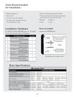
Parts Included Hardware Kit #5450M023-60 Use with metal cabinets. Surround the power cord opening. Cut to fit. Parts shown not to common scale. Basic Specifications Microwave Oven 60 Hz Max. Amp Usage Microwave UL Rating 1.60 kw 13.2 amps CSA Rating 1.5 kw 13.0 amps Convection UL Rating 1.60 kw - Viking VMOR205SS | Installation Instructions - Page 4
Convection Microwave Hood is designed for adaptation to three types of hood ventilation systems. Select the type required for your installation. Recirculating - non-vented, ductless. Follow installation procedure (A). Recirculating requires the use of the Charcoal Filter, which has been installed - Viking VMOR205SS | Installation Instructions - Page 5
the arrow. Using Tapping Screw 4x12 from the INSTALLATION HARDWARE, tighten into place. figure figure figure (A) Rotate 90˚ VERTICAL EXHAUST: Rotate hood fan unit 90˚ so that the fan blade openings are facing the top of the oven. Replace hood fan unit into oven unit. • Put the lead wire into the - Viking VMOR205SS | Installation Instructions - Page 6
figure figure figure figure figure Oven Installation figure figure figure THIS OVEN CANNOT BE PROPERLY INSTALLED WITHOUT REFERRING TO THE MOUNTING INSTRUCTIONS FOUND ON WALL AND TOP CABINET TEMPLATES. Mounting Plate • Separate 4 Toggle Bolts, packed in the INSTALLATION HARDWARE, from the Toggle - Viking VMOR205SS | Installation Instructions - Page 7
the carton portions together on the top of the range. Slide carton toward backguard until it stops. Align the lower back edge of the oven with the mounting plate. Thread the power supply cord through the hole made in the bottom of the top cabinet. figure ffiigguurree figurefigure (B) MOUNTING - Viking VMOR205SS | Installation Instructions - Page 8
to the top cabinet. Checklist for Installation • Make sure the unit has been installed according to all of the Installation Instructions and the Wall and Top Cabinet Templates. • Plug in the power cord. • Keep the Operation Manual. Viking Range Corporation 111 Front Street Greenwood, Mississippi - Viking VMOR205SS | Installation Instructions - Page 9
accomplie par un électricien qualifié avant que la Micro-ondes á Hotte et á Convection soit installée. Voir les 3 INSTRUCTIONS AU SOL ÉLECTRIQUES page F10. L'espace de support Cette Micro-ondes á Hotte et á Convection exige un espace de support sur un mur comme représenté sur le schéma 1. Elle est - Viking VMOR205SS | Installation Instructions - Page 10
au-dessus de l'endroit de support de micro-ondes á hotte et á convection comme montré en le schéma 2. REMARQUE : • Si vous avez n'importe quelles questions au sujet de fondre ou des instructions électriques, consultez un électricien ou un serviceperson qualifié. • Ni Viking ni le revendeur ne peut - Viking VMOR205SS | Installation Instructions - Page 11
pour la protection • Ciseaux • Measure • Crayon • Bande Matériel d'installation Le MATÉRIEL D'INSTALLATION (points 1 - 7) emballé avec le four devrait contenir ce qui suit: Pièces Inclus Kit de Matériel #5450M023-60 Article De Part Nom & Code Quantité 1 Vis en bois 5 x 30 millimètres - Viking VMOR205SS | Installation Instructions - Page 12
pi.) Système de ventilation (préparant le Coude 25˚ (25 pi.) Coude 45˚ (5 pi.) Chapeau mur (40 pi.) four pour l'installation) schéma schéma Cette Micro-ondes á Hotte et á Convection est conçue pour l'adaptation à trois types de systèmes de res de métal. age du cordon ventilation de capot - Viking VMOR205SS | Installation Instructions - Page 13
de 10 (10 pi.) Chapeaultoonigt e(2u4r vpoi.u)lue. (préparant le four pour l'installation) Coude 25˚ (25 pi.) Coude 45˚ (5 pi.) Chapeau mur (40 pi Horizontal : Attachez l'Assemblée d'amortisseur d'échappement au dos du plat de support en le glissant dans les fentes dans la même direction que la fl - Viking VMOR205SS | Installation Instructions - Page 14
ma CE FOUR NE PEUT PAS ÊTRE CORRECTEMENT INSTALLÉ SANS SE RAPPORTER AUX INSTRUCTIONS DE SUPPORT TROUVÉES SUR DES CALIBRES DE CABINET DE MUR ET DE DESSUS. Plat de support • Séparez 4 boulons à bascule, emballés dans le MATÉRIEL d'INSTALLATION, des écrous à bascule. Toggle Bolt Écrou À bascule sch - Viking VMOR205SS | Installation Instructions - Page 15
sch Installation de Four (A) (A) schéma schémsachéma sscchhéémmaa sscchhéémmaa schéma schéma (B) (B) (B) Four de support au mur : En utilisant la ligne de découpage autour du carton, de la coupe dans deux morceaux de (A) et (B). sscchhéémmaa schéma (B) Four de support au mur : Placez le - Viking VMOR205SS | Installation Instructions - Page 16
. La liste de contrôle pour l'installation • S'assurent l'unité a été installée selon tous les instructions d'installation et calibres de Cabinet de mur et de dessus. • Branchez le cordon de secteur. • Maintenez l'opération manuelle. Viking Range Corporation 111 Front Street Greenwood, Mississippi - Viking VMOR205SS | Installation Instructions - Page 17
Viking Instrucciones de Instalación Importante-Por favor lea y siga! • Lea una instalación y servicio adecuados, es necesario un espacio de 2 pulgadas entre la parte superior del protector trasero del horno y la parte inferior de la Campana del microondas por convección. figura 1 12" 30" 15.5" - Viking VMOR205SS | Installation Instructions - Page 18
que un electricista o mecánico calificado instale un tomacorriente cerca del artefacto. El cable encargado de brindar el servicio. • Ni Viking ni el distribuidor pueden aceptar ninguna responsabilidad longitud equivalente aproximada en pies de algunas partes de ducto típicas. Utilice los valores - Viking VMOR205SS | Installation Instructions - Page 19
Juego de tornillería #5450M023-60 Para uso en gabinetes metálicos. Bordee el orificio del cable de alimentación. Corte para ajustar. Las partes mostradas no reflejan su tamaño real. figura Especificaciones Básicas Horno Microondas Descripción VMOR205/DMOR206 Ancho total 29-15/16" (76.0 cm - Viking VMOR205SS | Installation Instructions - Page 20
(25 pies.) (40 pies.) ESCAPE HORIZONTAL: Gire la unidad de ventilador de la campana 180˚ para que los puertos de escape estén mirando a la parte posterior de la unidad del horno. figura ffiigguurraa • PRECAUCIÓN: No jale o estire los alambres del ventilador de la campana. • Coloque nuevamente la - Viking VMOR205SS | Installation Instructions - Page 21
figura figura ESCAPE VERTICAL: Gire la unidad de ventilador de la campana 90˚ para que los orificios de las paletas del ventilador estén mirando a la parte superior del horno. Coloque nuevamente la unidad de ventilador de la campana en la unidad del horno como se muestra en la figura !. • Coloque - Viking VMOR205SS | Installation Instructions - Page 22
figura figura figura figura Instalación del Horno figura figura figura ESTE HORNO NO PUEDE INSTALARSE APROPIADAMENTE SI NO SE CONSULTAN LAS INSTRUCCIONES DE MONTAJE QUE SE ENCUENTRAN EN LAS PLANTILLAS DE PARED Y DEL GABINETE SUPERIOR. Placa de Montaje • Separe 4 pernos acodados de la TORNILLER - Viking VMOR205SS | Installation Instructions - Page 23
de cartón, corte en dos piezas (A) y (B). ffiigguurraa figura (B) MONTAJE DEL HORNO A LA PARED: Coloque el horno y los pedazos de cartón juntos sobre la parte superior de la cocina. Deslice el cartón hacia el tope posterior hasta que se detenga. Alinee el borde posterior inferior del horno con la - Viking VMOR205SS | Installation Instructions - Page 24
(B) Instalación del Horno MONTAJE DEL HORNO A LA PARED: Instale los filtros de grasa encajándolos en la abertura. Presione y gabinete superior. • Enchufe el cable de alimentación. • Guarde el Manual de Operación. Viking Range Corporation 111 Front Street Greenwood, Mississippi 38930 EE.UU (662)
-
 1
1 -
 2
2 -
 3
3 -
 4
4 -
 5
5 -
 6
6 -
 7
7 -
8
-
9
-
10
-
11
-
12
-
13
-
14
-
15
-
16
-
17
-
18
-
19
-
20
-
21
-
22
-
23
-
24
 |
 |

Mounting Space
This Convection Microwave Hood requires a mounting
space on a wall as shown in figure
1
. It is designed to
be used with standard 12-inch wall cabinets.
For proper installation and servicing, a 2-inch space is
necessary between the top of the range backguard and
the bottom of the Convection Microwave Hood.
Wall Construction
This Convection Microwave Hood should be mounted
against and supported by a flat vertical wall. The wall
must be flat for proper installation. If the wall is not flat,
use spacers to fill in the gaps. Wall construction should
be a minimum of 2" x 4" wood studding and 3/8" or more
thick dry wall or plaster/lath. The mounting surfaces must
be capable of supporting a weight of 110 pounds—the
oven and contents—AND the weight of all items which
would normally be stored in the top cabinet above the
unit.
The unit should be attached to a minimum of one 2" x
4" wall stud or two 2" x 3" wall studs.
To find the location of the studs, one of the following
methods may be used:
•
Use a stud finder, a magnetic device which locates the
nails in the stud.
•
Use a hammer to tap lightly across the mounting
surface to find a solid sound. This will indicate stud
location.
The center of the stud can be located by probing the
wall with a small nail to find the edges of the stud and
then placing a mark halfway between the edges. The
center of any adjacent studs will normally be 16" or 24"
to either side of this mark.
Viking Installation Guide
Convection Microwave Hood
111 Front Street
Greenwood, Mississippi 38930 USA
IMPORTANT–Please Read and Follow!
•
Please read all instructions thoroughly before installing the Convection Microwave Hood. Two people are
recommended to install this product.
•
If a new electrical outlet is required, its installation should be completed by a qualified electrician before the
Convection Microwave Hood is installed. See 3 ELECTRICAL GROUNDING INSTRUCTIONS on page 2.
Backguard
At least 2"
15.5"
30"
12"
36" or more
from cooking
surface
72" or more
from floor
1