Whirlpool GT4175SPB Installation Instructions
Whirlpool GT4175SPB - Countertop Microwave Manual
 |
UPC - 050946956299
View all Whirlpool GT4175SPB manuals
Add to My Manuals
Save this manual to your list of manuals |
Whirlpool GT4175SPB manual content summary:
- Whirlpool GT4175SPB | Installation Instructions - Page 1
OVEN SAFETY 2 INSTALLATION INSTRUCTIONS 2 Tools Recommended 2 Parts Supplied 2 Cutout Dimensions 2 Electrical Requirements 3 Microwave Oven Preparation 3 Bottom Duct Assembly 3 Side Duct and Upper Duct Assembly 3 Anti-Tip Bracket Installation 4 Microwave Oven Placement 4 Trim Kit - Whirlpool GT4175SPB | Installation Instructions - Page 2
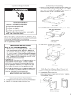
. Read and follow the instructions provided with any tools listed here. s Measuring tape s #2 Phillips screwdriver s Pencil s drill s Scissors Parts Supplied A B CD E Cutout Dimensions B A 16³⁄₄" (42.55 cm) 3" (7.6 cm) Width F G A. Trim kit frame B. Side duct (1) C. 1" screws - Whirlpool GT4175SPB | Installation Instructions - Page 3
are inside each support. Align the tab holes with the screw holes on the sides of the supports. Fasten supports to bottom microwave oven. SAVE THESE INSTRUCTIONS Microwave Oven Preparation 1. Unplug microwave oven before proceeding with installation. 2. Remove any loose items inside microwave oven - Whirlpool GT4175SPB | Installation Instructions - Page 4
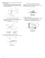
Be sure to align the centerline of template to centerline of cutout floor. (Dimensions as shown are not to scale.) B C A. Bottom duct B. Anti-tip bracket C. Bottom bracket 2. Plug in microwave oven. 3. Make sure microwave oven is centered within cutout opening and slide it into place, engaging anti - Whirlpool GT4175SPB | Installation Instructions - Page 5
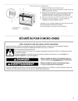
. Make sure orientation is correct as stated in Step 2. C. 1" screw D. Trim kit frame Installation is now complete. Replace any loose items that have been removed from microwave oven cavity. Save this installation instruction for future reference. SÉCURITÉ DU FOUR À MICRO-ONDES Votre sécurité et - Whirlpool GT4175SPB | Installation Instructions - Page 6
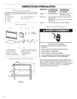
instructions fournies avec les outils indiqués ici. s Mètre-ruban s Tournevis Phillips nº 2 s Crayon s Foret de s Ciseaux Pièces fournies A B CD E DIMENSIONS bas (1) G. Supports de conduit du bas (2) H. Bride du fond (1) I. Conduit supérieur (1) J. Gabarit (1) Dimensions pour le dé - Whirlpool GT4175SPB | Installation Instructions - Page 7
un risque de choc électrique. L'utilisateur qui ne comprend pas bien les instructions de liaison à la terre, ou qui n'est pas certain que le intérieur du four à microondes. Assemblage du conduit du bas 1. Placer les supports sur les pattes de fixation des conduits sur le plancher. Veiller à ce que - Whirlpool GT4175SPB | Installation Instructions - Page 8
l'étape 2. L'installation est maintenant terminée. Remettre à l'intérieur du four à micro-ondes tout article qui en a été enlevé. Conserver ces instructions d'installation pour consultation ultérieure. 8205556/3828W5U0443 © 2004. All rights reserved. Tous droits réservés. 12/04 Printed in China
-
 1
1 -
 2
2 -
 3
3 -
 4
4 -
 5
5 -
 6
6 -
 7
7 -
8
 |
 |

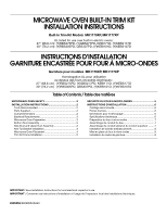
MICROWAVE OVEN BUILT-IN TRIM KIT
INSTALLATION INSTRUCTIONS
Built-In Trim Kit Models
MK1170XP, MK1177XP
INSTRUCTIONS D’INSTALLATION
GARNITURE ENCASTRÉE POUR FOUR À MICRO-ONDES
Garniture pour modèles
MK1170XP, MK1177XP
Homologation UL pour utilisation
au-dessus des fours encastrés électriques :
27" (68,6 cm) : (Y)RBS275PD, (Y)GBS277PD, KEBI171D, (Y)KEBS177D
30" (76,2 cm) : (Y)RBS305PD, GBS307PD, (Y)KEBI101D, (Y)KEBS107D
UL listed for use over built-in electric ovens:
27" (68.6 cm): (Y)RBS275PD, (Y)GBS277PD, KEBI171D, (Y)KEBS177D
30" (76.2 cm): (Y)RBS305PD, GBS307PD, (Y)KEBI101D, (Y)KEBS107D
Table of Contents / Table des matières
MICROWAVE OVEN SAFETY
................................................
2
INSTALLATION INSTRUCTIONS
..........................................
2
Tools Recommended
...........................................................
2
Parts Supplied
......................................................................
2
Cutout Dimensions
...............................................................
2
Electrical Requirements
........................................................
3
Microwave Oven Preparation
...............................................
3
Bottom Duct Assembly
........................................................
3
Side Duct and Upper Duct Assembly
..................................
3
Anti-Tip Bracket Installation
.................................................
4
Microwave Oven Placement
................................................
4
Trim Kit Frame Installation
....................................................
5
SÉCURITÉ DU FOUR À MICRO-ONDES
.................................
5
INSTRUCTIONS D'INSTALLATION
..........................................
6
Outillage recommandé
.............................................................
6
Pièces fournies
.........................................................................
6
Dimensions pour le découpage
...............................................
6
Spécifications électriques
........................................................
6
Préparation du four à micro-ondes
.........................................
7
Assemblage du conduit du bas
...............................................
7
Assemblage du conduit latéral et du conduit supérieur
.........
7
Installation de la bride antibasculement
..................................
8
Mise en place du four à micro-ondes
......................................
8
Installation du cadre de garniture
............................................
8
IMPORTANT:
Save Installation Instructions for local electrical inspector’s use.
IMPORTANT :
Conserver ces instructions d’installation à l’usage de l’inspecteur local des installations électriques.
8205556
/3828W5U0443