Whirlpool WED85HEFW Dimension Guide
Whirlpool WED85HEFW Manual
 |
View all Whirlpool WED85HEFW manuals
Add to My Manuals
Save this manual to your list of manuals |
Whirlpool WED85HEFW manual content summary:
- Whirlpool WED85HEFW | Dimension Guide - Page 1
. (984 mm) 39" Max. (990 mm) Side view: Electric Dryer 27" (686 mm) PRODUCT MODEL NUMBERS WED7505F, WED75HEF, WED7740F, servicing. ■■ Additional clearances might be required for wall, door, floor moldings, and dryer venting. ■■ Additional spacing should be considered on all sides of the dryer - Whirlpool WED85HEFW | Dimension Guide - Page 2
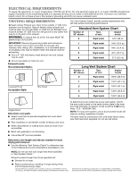
type code located on the serial number plate in the inner door well. Example: An electric model would be DALV (Long Vent) - ELE - XXXXXXX-XXX. NOTE: For long life of dryer. ■■ Reduce performance, resulting in longer drying times and increased energy usage. Because Whirlpool Corporation policy
-
 1
1 -
 2
2
 |
 |
Electric Dryer
PRODUCT MODEL NUMBERS
W10868947A
10/2016
WED7505F, WED75HEF, WED7740F, WED77HEF, WED8540F,
WED85HEF, WED90HEF, WED92HEF
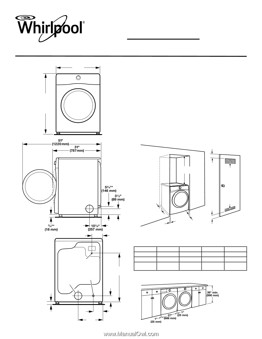
Dryer Dimensions
27"
(686 mm)
38
3
/
4
" Min.
(984 mm)
39" Max.
(990 mm)
Front view:
Side view:
Installation spacing for recessed area or closet
installation
All dimensions show recommended and minimum spacing
allowed.
■
Additional spacing should be considered for ease of
installation and servicing.
■
Additional clearances might be required for wall, door,
floor moldings, and dryer venting.
■
Additional spacing should be considered on all sides
of the dryer to reduce noise transfer.
■
For closet installation with a door, minimum ventilation
openings in the top and bottom of the door are required.
Louvered doors with equivalent ventilation openings are
acceptable.
■
Companion appliance spacing should also be considered.
Back view:
6
1
/
2
"
(165 mm)
29
7
/
8
"*
(759 mm)
3
1
/
2
"*
(89 mm)
6
1
/
8
"*
(156 mm)
14
3
/
8
"
(365 mm)
3
/
4
"*
(18 mm)
NOTE:
Most
installations
require a minimum
of 5" (127 mm)
clearance behind
dryer for exhaust
vent with elbow.
See “Venting
Requirements.”
*Approx. measurement.
Power supply
cord/cable
Water inlet
(Steam
models
only)
Vent
Recommended installation clearances (dryer only):
*0" (0 mm) spacing is allowed for straight-back venting only.
For steam models only, inlet hose must not be kinked.
Front
Sides
Rear
Top
Recessed
NA
0" (0 mm)
0" (0 mm)**
0" (0 mm)
Closet
NA
0" (0 mm)
0" (0 mm)**
0" (0 mm)
Under
Counter
NA
1” (25 mm)
0” (0 mm)**
0” (0 mm)
Minimum installation clearances (dryer only):
**0
"
(0 mm) spacing is allowed for straight-back venting only.
18" min.
(457 mm)
1"*
(25 mm)
0" - 5"*
(0" - 127 mm)
24 in.
2
min.
(155 cm
2
)
48 in.
2
min.
(310 cm
2
)
3"
(76 mm)
3"
(76 mm)
1"
(25 mm)
0
"
–5"*
(0 mm–127 mm)
Custom under counter installation: