Whirlpool WFG381LVQ Installation Guide
Whirlpool WFG381LVQ - 30 Inch Range Manual
 |
UPC - 883049139296
View all Whirlpool WFG381LVQ manuals
Add to My Manuals
Save this manual to your list of manuals |
Whirlpool WFG381LVQ manual content summary:
- Whirlpool WFG381LVQ | Installation Guide - Page 1
30" (76.2 CM) FREESTANDING GAS RANGES INSTRUCTIONS D'INSTALLATION DES CUISINIÈRES À GAZ AUTOPORTANTES DE 30" (76,2 CM) Table of Contents/Table des matières RANGE SAFETY 2 SÉCURITÉ DE LA CUISINIÈRE 19 INSTALLATION REQUIREMENTS 3 EXIGENCES D'INSTALLATION 20 Tools and Parts 3 Outillage et pièces - Whirlpool WFG381LVQ | Installation Guide - Page 2
light any appliance. • Do not touch any electrical switch. • Do not use any phone in your building. • Immediately call your gas supplier from a neighbor's phone. Follow the gas supplier's instructions. • If you cannot reach your gas supplier, call the fire department. - Installation and service must - Whirlpool WFG381LVQ | Installation Guide - Page 3
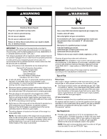
if the range is moved. Failure to follow these instructions can result in death or serious burns to children and adults. INSTALLATION REQUIREMENTS Tools and Parts Gather the required tools and parts before starting installation. Read and follow the instructions provided with any tools listed here - Whirlpool WFG381LVQ | Installation Guide - Page 4
36" (91.4 cm) countertop height. IMPORTANT: If installing a range hood or microwave hood combination above the range, follow the range hood or microwave hood combination installation instructions for dimensional clearances above the cooktop surface. D B C F BC E D A. 27 69.9 cm) max. depth with - Whirlpool WFG381LVQ | Installation Guide - Page 5
. If the types of gas listed do not include the type of gas available, check with the local gas supplier. LP gas conversion: Conversion must be done by a qualified service technician. No attempt shall be made to convert the appliance from the gas specified on the model/serial rating plate for use - Whirlpool WFG381LVQ | Installation Guide - Page 6
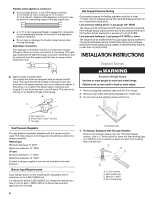
) or lower The range must be isolated from the gas supply piping system by closing its individual manual shutoff valve during any pressure testing of the gas supply piping system at test pressures equal to or less than ½ psi (3.5 kPa). INSTALLATION INSTRUCTIONS Unpack Range WARNING Excessive Weight - Whirlpool WFG381LVQ | Installation Guide - Page 7
mounting holes through your type of floor covering. Before moving range, slide range onto shipping base, cardboard or hardboard. 1. Remove template from the anti-tip bracket kit (found inside the oven cavity) or from the back of this manual. 2. Place template on the floor in cabinet opening so that - Whirlpool WFG381LVQ | Installation Guide - Page 8
is parallel to the gas pipe. A B A. Closed valve B. Open valve 3. Test all connections by brushing on an approved noncorrosive leak-detection solution. If bubbles appear, a leak is indicated. Correct any leak found. 4. Remove cooktop burner caps and grates from parts package. Burner caps should be - Whirlpool WFG381LVQ | Installation Guide - Page 9
instructions can result in death, fire, or electrical shock. 5. Plug into a grounded 3 prong outlet. Verify Anti-Tip Bracket Location 1. On models Range must be level for satisfactory baking performance. Electronic Ignition System Initial lighting and gas flame adjustments Cooktop and oven burners - Whirlpool WFG381LVQ | Installation Guide - Page 10
and broil burners. Refer to the Use and Care Guide for proper operation of the oven controls. Adjust Oven Bake Burner Flame (if needed) 1. On models with a occur. 3. If the oven bake flame needs to be adjusted, locate the air shutter near the center rear of the range. Loosen the locking screw and - Whirlpool WFG381LVQ | Installation Guide - Page 11
and Care Guide for proper operation of the oven controls. Adjust Oven Broil Burner Flame (if needed) Look through oven window to check broil burner for proper . Warming Drawer (on some models) Remove all items from inside the warming drawer, and allow the range to cool completely before attempting - Whirlpool WFG381LVQ | Installation Guide - Page 12
a soft cloth. For more information, see the "Range Care" section of the Use and Care Guide. 6. Read the Use and Care Guide. 7. Turn on surface burners and oven. See the Use and Care Guide for specific instruction on range operation. If range does not operate, check the following: ■ Household fuse - Whirlpool WFG381LVQ | Installation Guide - Page 13
is moved. Failure to follow these instructions can result in death or serious burns to children and adults. 1. Turn the manual shutoff valve to the closed position. B A C A. To range B. Manual shutoff valve "closed" position C. Gas supply line 2. Unplug range or disconnect power. C Side view after - Whirlpool WFG381LVQ | Installation Guide - Page 14
base. NOTE: Reinstall one of the screws through the range cooktop to hold the orifice spud holder in place while removing and replacing the orifice spuds. C A D B A. Igniter electrode B. Gas tube opening C. Burner cap D. Burner base 3. Apply masking tape to the end of a 7 mm nut driver to help - Whirlpool WFG381LVQ | Installation Guide - Page 15
, disconnect the igniter wire, and set the bake burner aside on a covered surface. B To Convert Oven Broil Burner (Natural Gas to LP Gas) 1. Remove the screw from the broil burner. 2. Remove the broil burner from the broil burner orifice hood. NOTE: The broil burner will hang in the back of the - Whirlpool WFG381LVQ | Installation Guide - Page 16
drawing. 6. Replace plastic cover over gas pressure regulator cap. To Convert Surface Burners (LP Gas to Natural Gas) 1. Remove burner cap. 2. Using a Phillips or Quadrex® screwdriver, remove the burner base. NOTE: Reinstall one of the screws through the range cooktop to hold the orifice spud holder - Whirlpool WFG381LVQ | Installation Guide - Page 17
N180 N155 N140 N110 NOTE: Refer to the Model Number and Serial Number Plate located on the oven frame behind the top left side of the oven door for proper sizing of spuds for each burner location. 5. Place LP gas orifice spuds in plastic parts bag for future use and keep with package containing - Whirlpool WFG381LVQ | Installation Guide - Page 18
burner. Checking for proper cooktop, bake and broil burner flame is very important. Natural gas flames do not have yellow tips. 3. Refer to "Complete Installation" in the "Installation Instructions" section of this manual to complete this procedure. C A. Broil burner B. Screws C. Orifice hood - Whirlpool WFG381LVQ | Installation Guide - Page 19
et ce qui peut se produire en cas de non-respect des instructions. AVERTISSEMENT : Si les renseignements dans ce manuel ne sont pas exactement entretien doivent être effectués par un installateur qualifié, une agence de service ou le fournisseur de gaz. AVERTISSEMENT : L'odorat ne permet pas - Whirlpool WFG381LVQ | Installation Guide - Page 20
au pied arrière de la cuisinière. Joindre de nouveau la bride antibasculement si la cuisinière est déplacée. Le non-respect de ces instructions peut causer un décès ou des brûlures graves aux enfants et aux adultes. EXIGENCES D'INSTALLATION Outillage et pièces Avant d'entreprendre l'installation - Whirlpool WFG381LVQ | Installation Guide - Page 21
conforme aux dispositions de la norme Manufactured Home Construction and Safety Standard, Title 24 CFR, Part 3280 (anciennement Federal Standard for Mobile Home Construction and Safety, Title 24, HUD Part 280). Lorsque cette norme n'est pas applicable, l'installation doit satisfaire aux critères de - Whirlpool WFG381LVQ | Installation Guide - Page 22
la broche de liaison à la terre. Ne pas utiliser un adaptateur. Ne pas utiliser un câble de rallonge. Le non-respect de ces instructions peut causer un décès, un incendie ou un choc électrique. IMPORTANT : La cuisinière doit être électriquement reliée à la terre conformément aux prescriptions - Whirlpool WFG381LVQ | Installation Guide - Page 23
satisfaire aux prescriptions de la plus récente édition du : National Fuel Gas Code ANSI Z223.1 (American National Standard), ou CAN/CGA B149 (édition tests de fuite de la cuisinière doivent être effectués selon les instructions du fabricant. Type de gaz Gaz naturel : La conception de cette cuisini - Whirlpool WFG381LVQ | Installation Guide - Page 24
Raccordement par une canalisation rigide : On doit utiliser une combinaison de raccords pour réaliser un raccordement rigide entre la cuisinière et la canalisation de gaz. La canalisation rigide doit se trouver au même niveau que le raccord de connexion de la cuisinière. On doit veiller à ne - Whirlpool WFG381LVQ | Installation Guide - Page 25
pour déplacer et installer la cuisinière. Le non-respect de cette instruction peut causer une blessure au dos ou d'autre blessure. Sur les cuisinières antibasculement si la cuisinière est déplacée. Le non-respect de ces instructions peut causer un décès ou des brûlures graves aux enfants et aux - Whirlpool WFG381LVQ | Installation Guide - Page 26
: le personnel autorisé de chauffage, le personnel autorisé d'une compagnie de gaz, et le personnel d'entretien autorisé. Le non-respect de ces instructions peut causer un décès, une explosion ou un incendie. En fonction de l'épaisseur du plancher, des vis plus longues peuvent s'avérer nécessaires - Whirlpool WFG381LVQ | Installation Guide - Page 27
pas enlever la broche de liaison à la terre. Ne pas utiliser un adaptateur. Ne pas utiliser un câble de rallonge. Le non-respect de ces instructions peut causer un décès, un incendie ou un choc électrique. 5. Brancher sur une prise à 3 alvéoles reliée à la terre. 27 - Whirlpool WFG381LVQ | Installation Guide - Page 28
Vérification de l'emplacement de la bride antibasculement 1. Sur les modèles avec tiroir de remisage, retirer le tiroir de remisage. Voir la section "Tiroir de remisage". Sur les modèles avec tiroir-réchaud, retirer le tiroir ne permet pas de visualiser le pied arrière. Il convient de visualiser le - Whirlpool WFG381LVQ | Installation Guide - Page 29
ne survenir qu'après 50 à 60 secondes. Un dispositif d'allumage électronique est utilisé pour l'allumage des brûleurs du four et du gril. Consulter le Guide d'utilisation et d'entretien pour le bon fonctionnement des commandes du four. Réglage de la taille des flammes sur le brûleur du four (le cas - Whirlpool WFG381LVQ | Installation Guide - Page 30
Le brûleur du four devrait s'allumer en moins de 8 secondes; dans certaines conditions, l'allumage peut ne survenir qu'après 50 à 60 secondes. Consulter le Guide d'utilisation et d'entretien pour le bon fonctionnement des commandes du four. Réglage de la taille des flammes sur le brûleur du gril (le - Whirlpool WFG381LVQ | Installation Guide - Page 31
la porte du four pour une utilisation normale. Toutefois, si la dépose est nécessaire, s'assurer que le four est éteint et froid. Puis, suivre ces instructions. La porte du four est lourde. Dépose : 1. Ouvrir la porte du four complètement. 2. Pincer le loquet de charnière entre deux doigts et tirer - Whirlpool WFG381LVQ | Installation Guide - Page 32
de surface et le four. Pour des instructions spécifiques concernant l'utilisation de la cuisinière, consulter le Guide d'utilisation et d'entretien. Si la cuisini besoin d'assistance ou de service : Veuillez consulter la section "Assistance ou service" dans le Guide d'utilisation et d'entretien ou - Whirlpool WFG381LVQ | Installation Guide - Page 33
tourner dans le sens antihoraire et soulever pour enlever le gicleur. Conserver à part le gicleur du brûleur. C A D LP C Vue de côté couvercle de plastique par-dessus le capuchon du détendeur. LP B A. Gicleur B. Support du gicleur C. Vis D. Électrode d'étincelle 4. Retirer le porte-gicleur de - Whirlpool WFG381LVQ | Installation Guide - Page 34
Gicleur pour propane pour brûleurs de surface Puissance thermique Couleur Taille Code d'identification 14 000 BTU 11 000 BTU 8 000 BTU 5 000 BTU Jaune/Orange Jaune/Marron Jaune/Noir Jaune/Blanc 1,07 mm 0,99 mm 0,85 mm 0,70 mm L107 L99 L85 L70 REMARQUE : Voir la plaque signalétique située - Whirlpool WFG381LVQ | Installation Guide - Page 35
au pied arrière de la cuisinière. Joindre de nouveau la bride antibasculement si la cuisinière est déplacée. Le non-respect de ces instructions peut causer un décès ou des brûlures graves aux enfants et aux adultes. 1. Tourner le robinet d'arrêt manuel pour le placer à la position de fermeture - Whirlpool WFG381LVQ | Installation Guide - Page 36
faire tourner dans le sens antihoraire et soulever pour enlever le gicleur. Conserver à part le gicleur du brûleur. C A D B A. Détendeur IMPORTANT : Ne rations de retrait et de remplacement des gicleurs. 36 A. Gicleur B. Support du gicleur C. Vis D. Électrode d'étincelle 4. Chaque gicleur est - Whirlpool WFG381LVQ | Installation Guide - Page 37
Conversion du brûleur de cuisson au four (de gaz propane à gaz naturel) 1. Retirer les grilles du four. 2. Ôter 2 vis à l'arrière de la partie inférieure du four. 3. Soulever l'arrière de la partie inférieure du four vers le haut et l'arrière jusqu'à ce que l'avant du panneau se trouve hors du cadre - Whirlpool WFG381LVQ | Installation Guide - Page 38
du four. Les flammes d'un brûleur alimenté au gaz naturel ne comportent pas de pointe jaune. 3. Voir le paragraphe "Achever l'installation" de la section "Instructions d'installation" du présent manuel pour achever cette procédure. 38 - Whirlpool WFG381LVQ | Installation Guide - Page 39
et le bord supérieur contre la paroi arrière. Top edge Bord supérieur Use this template to anchor the left rear leg of range. Utiliser ce gabarit pour ancrer le pied arrière gauche de la cuisinière. 39 - Whirlpool WFG381LVQ | Installation Guide - Page 40
W10413013A © 2011. All rights reserved. Tous droits réservés. 5/11 Printed in U.S.A. Imprimé aux É.-U.
-
 1
1 -
 2
2 -
 3
3 -
 4
4 -
 5
5 -
 6
6 -
 7
7 -
8
-
9
-
10
-
11
-
12
-
13
-
14
-
15
-
16
-
17
-
18
-
19
-
20
-
21
-
22
-
23
-
24
-
25
-
26
-
27
-
28
-
29
-
30
-
31
-
32
-
33
-
34
-
35
-
36
-
37
-
38
-
39
-
40
 |
 |

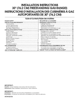
INSTALLATION INSTRUCTIONS
30" (76.2 CM) FREESTANDING GAS RANGES
INSTRUCTIONS D’INSTALLATION DES CUISINIÈRES À GAZ
AUTOPORTANTES DE 30" (76,2 CM)
Table of Contents/Table des matières
RANGE SAFETY
.............................................................................
2
INSTALLATION REQUIREMENTS
...............................................
3
Tools and Parts
............................................................................
3
Location Requirements
...............................................................
3
Electrical Requirements
...............................................................
5
Gas Supply Requirements
...........................................................
5
INSTALLATION INSTRUCTIONS
.................................................
6
Unpack Range
.............................................................................
6
Install Anti-Tip Bracket
................................................................
7
Make Gas Connection
.................................................................
8
Verify Anti-Tip Bracket Location
..................................................
9
Level Range
.................................................................................
9
Electronic Ignition System
...........................................................
9
Warming Drawer
........................................................................
11
Storage Drawer
..........................................................................
11
Oven Door
..................................................................................
12
Complete Installation
.................................................................
12
GAS CONVERSIONS
...................................................................
13
LP Gas Conversion
....................................................................
13
Natural Gas Conversion
............................................................
16
ANTI-TIP BRACKET TEMPLATE
................................................
39
SÉCURITÉ DE LA CUISINIÈRE
...................................................
19
EXIGENCES D’INSTALLATION
...................................................
20
Outillage et pièces
......................................................................
20
Exigences d'emplacement
.........................................................
21
Spécifications électriques
..........................................................
22
Spécifications de l’alimentation en gaz
.....................................
23
INSTRUCTIONS D'INSTALLATION
............................................
25
Déballage de la cuisinière
..........................................................
25
Installation de la bride antibasculement
....................................
25
Raccordement à la canalisation de gaz
.....................................
26
Vérification de l'emplacement de la bride antibasculement
.....
28
Mise à niveau de la cuisinière
....................................................
28
Système d'allumage électronique
.............................................
28
Tiroir-réchaud
.............................................................................
30
Tiroir de Remisage
.....................................................................
30
Porte du four
..............................................................................
31
Achever l’installation
..................................................................
32
CONVERSIONS POUR CHANGEMENT DE GAZ
......................
32
Conversion pour l'alimentation au propane
..............................
32
Conversion pour l'alimentation au gaz naturel
..........................
35
GABARIT POUR LA BRIDE ANTIBASCULEMENT
....................
39
IMPORTANT:
Installer:
Leave installation instructions with the homeowner.
Homeowner:
Keep installation instructions for future reference.
IMPORTANT :
Installateur :
Remettre les instructions d'installation au propriétaire.
Propriétaire :
Conserver les instructions d'installation pour référence ultérieure.
W10413013A