Yamaha RX-V567 Component Hookup Diagram
Yamaha RX-V567 Manual
 |
UPC - 027108935980
View all Yamaha RX-V567 manuals
Add to My Manuals
Save this manual to your list of manuals |
Yamaha RX-V567 manual content summary:
- Yamaha RX-V567 | Component Hookup Diagram - Page 1
RX-V567/HTR-5063 HDMI Blu-ray/DVD, Cable/SAT and Component Video Game CENTER SPEAKERS SURROUND SURROUND BACK/ BI-AMP SINGLE OPTICAL AV 1 COAXIAL AV 2 COAXIAL (CD) AV 3 OPTICAL ( TV ) AV 4 AV 5 AV 6 AV OUT AUDIO 1 AUDIO 2 AUDIO OUT COMPONENT VIDEO PR PB Y AV 1 COMPONENT VIDEO PR PB Y - Yamaha RX-V567 | Component Hookup Diagram - Page 2
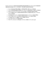
AV1 on the Receiver Remote Control. 4. Press the Option button on Receiver Remote Control and Volume Trim appear on the front display of Receiver. 5. Using Arrow down button on Receiver Remote Control, scroll down to Audio In Menu. 6. Press the Enter button on the Receiver Remote Control to enter
-
 1
1 -
 2
2
 |
 |
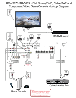
BD/DVD player
Game Console
TV
Cable/Satellite Box
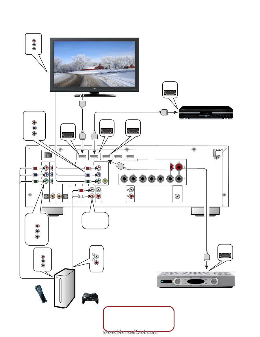
RX-V567/HTR-5063 HDMI Blu-ray/DVD, Cable/SAT and
Component Video Game Console Hookup Diagram
COMPONENT
VIDEO
L
A
C
I
T
P
O
L
A
C
I
T
P
O
( TV )
V
A
1
V
A
2
V
A
3
V
A
4
V
A
5
V
A
6
D
U
A
1
O
I
2
O
I
D
U
A
COAXIAL
COAXIAL
(CD)
SINGLE
SURROUND BACK/
BI-AMP
(BD/DVD)
HDMI 2
3
I
M
D
H
1
I
M
D
H
HDMI 4
HDMI
OUT
OUT
SUBWOOFER
AUDIO
PRE OUT
OUT
DOCK
ANTENNA
MONITOR OUT
COMPONENT
VIDEO
VIDEO
SPEAKERS
COMPONENT
VIDEO
P
R
P
B
Y
INPUT
MONITOR OUT
COMPONENT
VIDEO
P
R
P
B
Y
COMPONENT
VIDEO
P
R
P
B
Y
AV 1
OUT
HDMI
OUT
HDMI
OUT
HDMI
IN 1
HDMI
IN 2
HDMI
*See Notes For
Input Configuration
Below
Notes:
The Component Input AV #1 will need to be
associated to the Audio #1 input.
Please
see page 2 of this document for detailed
instructions on setting that feature up.
Stereo Left & Right
Analog Audio 1
AUDIO
R
L
OUTPUT
COMPONENT
VIDEO
P
R
P
B
Y
OUTPUT