Zenith 121AC-A Installation Instructions
Zenith 121AC-A - Heath - Lock Nut Transformer Manual
 |
UPC - 011009525081
View all Zenith 121AC-A manuals
Add to My Manuals
Save this manual to your list of manuals |
Zenith 121AC-A manual content summary:
- Zenith 121AC-A | Installation Instructions - Page 1
on transformer (see wiring diagram included with the chime, bell, or buzzer). For Model 125C Only: See arrow markings on transformer to determine correct screw terminals for 8, 16, or 24 volt connection. TO REPLACE EXISTING TRANSFORMER, FOLLOW INSTRUCTIONS ABOVE (OMIT STEP 2). LABEL WIRES PRIOR - Zenith 121AC-A | Installation Instructions - Page 2
axe fileté du transformateur, à l'intérieur de la boîte de jonction (voir fig. 1). Montage du transformateur de type à patte d'attache (modèles 107C et 125C) : Remarque : La patte d'attache nécessite une boîte de jonction dotée de côtés plats et d'alvéoles défonçables. À partir de l'extérieur de la
-
 1
1 -
 2
2
 |
 |

TRANSFORMER INSTALLATION INSTRUCTIONS
IMPORTANT:
READ ALL INSTRUCTIONS BEFORE INSTALLING TRANSFORMER.
FOLLOW ALL NATIONAL AND LOCAL ELECTRICAL CODES.
CONTACT A QUALIFIED ELECTRICIAN IF THERE ARE ANY QUESTIONS AS TO THE SUITABILITY OF THE SYSTEM.
1. WARNING:
TURN OFF POWER AT FUSE OR JUNCTION BOX BEFORE INSTALLING TRANSFORMER.
2.
Locate or install a junction box close to the selected mounting location for your chime. Do not install transformer in an
attic location. For new installation remove cover plate and knockout from junction box.
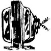
3. Mounting locknut type transformer (Models 121AC and 122C):
From exterior of junction box, pass transformer wires
through hole in junction box. To secure transformer to junction box, fasten locknut to transformer’s threaded shaft on
inside of junction box (see Figure 1).
Mounting clamp type transformer (Models 107C and 125C):
Note:
Mounting clamp requires a junction box with flat
sides and knockouts. From exterior of junction box, pass transformer wires through knockout hole in junction box. Insert
transformer clamp through same knockout hole as wires. Tighten screw (provided) against edge of knockout hole on
junction box (see Figure 2).
4. Connecting Transformer Wires to Power Wires:
If necessary, strip 1/2” of insulation from power supply wires (see
Figure 3). Twist black wire lead from transformer to black wire lead from power supply. Twist white wire lead from trans-
former to white wire lead from power supply. Twist green ground wire from transformer to bare (or green insulated)
copper lead of power supply. For metal junction boxes, it is required to connect green ground wire from transformer to
the metal junction box or clamp it to the metal conduit.
Insulate each connection using UL Approved wire nut (see Figure 4).
5.
Check all connections and replace cover plate.
6.
Attach low voltage wires from chime, bell, or buzzer to secondary screw terminals on transformer (see wiring diagram
included with the chime, bell, or buzzer).
For Model 125C Only:
See arrow markings on transformer to determine correct screw terminals for 8, 16, or 24 volt
connection.
TO REPLACE EXISTING TRANSFORMER, FOLLOW INSTRUCTIONS ABOVE (OMIT STEP 2). LABEL WIRES PRIOR
TO REMOVAL OF EXISTING TRANSFORMER.
P.O. Box 90045
Bowling Green, KY 42102-9045
Figure / Figura 1
Figure / Figura 2
1/2"
Figure / Figura 3
Figure / Figura 4
© 2008 HeathCo LLC
598-1110-06