2002 Ford Crown Victoria Natural Gas Vehicle Supplement 1st Printing - Page 10
2002 Ford Crown Victoria Manual
Page 10 highlights
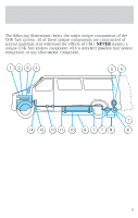
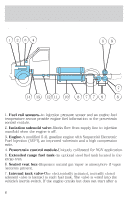
Servicing your vehicle 12. Two fuel tanks-Located underbody to facilitate fuel system design. 13. Stone and heat shield-Protective shield able to prevent damage to the fuel tanks caused by road debris or other road hazards. 14. High pressure fuel lines-Delivers high pressure fuel to the pressure regulator. 15. Pressure regulator and coalescent fuel filter assembly-Reduces the fuel pressure to the fuel injection pressure of 125 psi. 16. Quarter turn valve-Isolates the fuel tanks from the rest of the fuel system. 17. Low pressure fuel lines-Supplies 125 psi of natural gas to the engine. 18. Fuel rail sensors-One injection pressure sensor and two engine fuel temperature sensors provide engine fuel information to the PCM. ADAPTERS DO NOT use fuel receptacle adapters when refueling your vehicle. The profiles of both the natural gas vehicle receptacle and the fuel station nozzles are specified by ANSI/AGA NGV1-1994, CGA NGV1-M94. These profiles are specified for compressed natural gas vehicles and fuel stations for safety purposes. Three separate adapter profiles are available. P24, P30 and P36 respectively, are specified for the three different service pressures of 16 500 kPa (2 400 psi), 20 700 kPa (3 000 psi) and 24 800 kPa (3 600 psi). Your vehicle's service pressure may be 20 700 kPa (3 000 psi) or 24 800 kPa (3 600 psi), depending upon application. Refer to the label on the fuel filler door: • If your vehicle's fuel system is rated at 20 700 kPa (3 000 psi), it can be refueled using a P30 or P24 nozzle. However, use of a P24 nozzle will result in an incomplete fill. • If your vehicle's fuel system is rated at 24 800 kPa (3 600 psi), it is refueled using a P36 nozzle only. DO NOT over pressurize the CNG fuel system or damage to the fuel system and possible personal injury may occur. 10
-
 1
1 -
2
-
3
-
4
-
 5
5 -
 6
6 -
 7
7 -
 8
8 -
 9
9 -
 10
10 -
 11
11 -
 12
12 -
 13
13 -
 14
14 -
 15
15 -
16
 |
 |