2006 Ford F250 Owner Guide 2nd Printing - Page 65
2006 Ford F250 Manual
Page 65 highlights
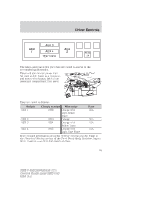
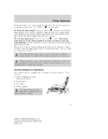
Driver Controls The relays and fuse in the glove box are coded as shown in the accompanying illustration. There will also be one power lead for each switch found as a blunt-cut and sealed wire located behind the passenger compartment fuse panel. They are coded as follows: Switch AUX 1 Circuit number Wire color 1936 Orange with Light Green Trace 1933 Orange 1934 Orange with Yellow Trace 1935 Orange with Light Blue Trace Fuse 30A AUX 2 AUX 3 AUX 4 30A 10A 10A More detailed information about the Upfitter switches can be found in the Electrical Wiring section of the Ford Truck Body Builders Layout Book, found at www.fleet.ford.com/truckbbas. 65 2006 F-250/350/450/550 (f23) Owners Guide (post-2002-fmt) USA (fus)
-
 1
1 -
2
-
3
-
4
-
5
-
6
-
7
-
8
-
9
-
10
-
11
-
12
-
13
-
14
-
15
-
16
-
17
-
18
-
19
-
20
-
21
-
22
-
23
-
24
-
25
-
26
-
27
-
28
-
29
-
30
-
31
-
32
-
33
-
34
-
35
-
36
-
37
-
38
-
39
-
40
-
41
-
42
-
43
-
44
-
45
-
46
-
47
-
48
-
49
-
50
-
51
-
52
-
53
-
54
-
55
-
56
-
57
-
58
-
59
-
 60
60 -
 61
61 -
 62
62 -
 63
63 -
 64
64 -
 65
65 -
 66
66 -
 67
67 -
 68
68 -
 69
69 -
 70
70 -
71
-
72
-
73
-
74
-
75
-
76
-
77
-
78
-
79
-
80
-
81
-
82
-
83
-
84
-
85
-
86
-
87
-
88
-
89
-
90
-
91
-
92
-
93
-
94
-
95
-
96
-
97
-
98
-
99
-
100
-
101
-
102
-
103
-
104
-
105
-
106
-
107
-
108
-
109
-
110
-
111
-
112
-
113
-
114
-
115
-
116
-
117
-
118
-
119
-
120
-
121
-
122
-
123
-
124
-
125
-
126
-
127
-
128
-
129
-
130
-
131
-
132
-
133
-
134
-
135
-
136
-
137
-
138
-
139
-
140
-
141
-
142
-
143
-
144
-
145
-
146
-
147
-
148
-
149
-
150
-
151
-
152
-
153
-
154
-
155
-
156
-
157
-
158
-
159
-
160
-
161
-
162
-
163
-
164
-
165
-
166
-
167
-
168
-
169
-
170
-
171
-
172
-
173
-
174
-
175
-
176
-
177
-
178
-
179
-
180
-
181
-
182
-
183
-
184
-
185
-
186
-
187
-
188
-
189
-
190
-
191
-
192
-
193
-
194
-
195
-
196
-
197
-
198
-
199
-
200
-
201
-
202
-
203
-
204
-
205
-
206
-
207
-
208
-
209
-
210
-
211
-
212
-
213
-
214
-
215
-
216
-
217
-
218
-
219
-
220
-
221
-
222
-
223
-
224
-
225
-
226
-
227
-
228
-
229
-
230
-
231
-
232
-
233
-
234
-
235
-
236
-
237
-
238
-
239
-
240
-
241
-
242
-
243
-
244
-
245
-
246
-
247
-
248
-
249
-
250
-
251
-
252
-
253
-
254
-
255
-
256
-
257
-
258
-
259
-
260
-
261
-
262
-
263
-
264
-
265
-
266
-
267
-
268
-
269
-
270
-
271
-
272
-
273
-
274
-
275
-
276
-
277
-
278
-
279
-
280
-
281
-
282
-
283
-
284
-
285
-
286
-
287
-
288
-
289
-
290
-
291
-
292
-
293
-
294
-
295
-
296
-
297
-
298
-
299
-
300
-
301
-
302
-
303
-
304
-
305
-
306
-
307
-
308
-
309
-
310
-
311
-
312
 |
 |
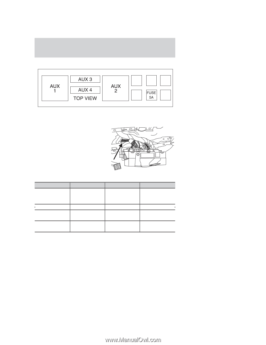
The relays and fuse in the glove box are coded as shown in the
accompanying illustration.
There will also be one power lead
for each switch found as a blunt-cut
and sealed wire located behind the
passenger compartment fuse panel.
They are coded as follows:
Switch
Circuit number
Wire color
Fuse
AUX 1
1936
Orange with
Light Green
Trace
30A
AUX 2
1933
Orange
30A
AUX 3
1934
Orange with
Yellow Trace
10A
AUX 4
1935
Orange with
Light Blue Trace
10A
More detailed information about the Upfitter switches can be found in
the
Electrical Wiring
section of the
Ford Truck Body Builders Layout
Book
, found at www.fleet.ford.com/truckbbas.
2006 F-250/350/450/550
(f23)
Owners Guide (post-2002-fmt)
USA
(fus)
Driver Controls
65