3Com 2426-PWR User Guide - Page 50
Setting Up Two VLANs on the Same Switch, Setting Up VLAN Across Two Switches, Setup
 |
UPC - 662705550237
View all 3Com 2426-PWR manuals
Add to My Manuals
Save this manual to your list of manuals |
Page 50 highlights
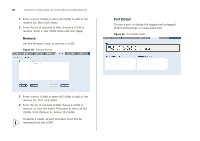
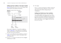
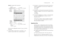
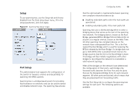
50 CHAPTER 4: CONFIGURING THE SWITCH FROM THE WEB INTERFACE Setting Up Two VLANs on the Same Switch Figure 38 illustrates how you can set up a simple VLAN on the Switch using desktop connections. Figure 38 Desktop VLAN Configuration Endstations in VLAN 1 Endstations in VLAN 2 Baseline Switch 3 Click Apply. Ports 1, 3, and 26 now belong to VLAN2, and will not communicate with any other ports, unless you add other ports to the VLAN or change the port configuration. Setting Up VLAN Across Two Switches This example explains how you can set up a VLAN across two Switches using Tagged ports. This enables ports that are members of the same VLAN (but are on different switches) to communicate, provided that a port on each Switch is set to Tagged, and that these ports are connected. Server Server in VLAN 1 in VLAN 2 If you want to add ports 1, 3, and 26 to VLAN2 (as shown in Figure 38), so that the ports on the default VLAN1 and the ports on VLAN2 cannot communicate with each other, do the following: 1 Create a new VLAN and set the VLAN ID to 2. Refer to "Setup" for instructions. VLAN1 is the default VLAN and already exists. 2 Set ports 1, 3, and 26 to associate with the Untagged membership in VLAN2.
-
 1
1 -
2
-
3
-
4
-
5
-
6
-
7
-
8
-
9
-
10
-
11
-
12
-
13
-
14
-
15
-
16
-
17
-
18
-
19
-
20
-
21
-
22
-
23
-
24
-
25
-
26
-
27
-
28
-
29
-
30
-
31
-
32
-
33
-
34
-
35
-
36
-
37
-
38
-
39
-
40
-
41
-
42
-
43
-
44
-
 45
45 -
 46
46 -
 47
47 -
 48
48 -
 49
49 -
 50
50 -
 51
51 -
 52
52 -
 53
53 -
 54
54 -
 55
55 -
56
-
57
-
58
-
59
-
60
-
61
-
62
-
63
-
64
-
65
-
66
-
67
-
68
-
69
-
70
-
71
-
72
-
73
-
74
-
75
-
76
-
77
-
78
-
79
-
80
-
81
-
82
-
83
-
84
-
85
-
86
-
87
-
88
-
89
-
90
-
91
-
92
-
93
-
94
-
95
-
96
-
97
-
98
-
99
-
100
-
101
-
102
-
103
-
104
-
105
-
106
-
107
-
108
 |
 |
