3Ware 9550SXU-4LP-SGL Quick Installation Guide - Page 21
Connecting Drive Activity LED Indicators, - 9550sx 4lp
 |
UPC - 693494980042
View all 3Ware 9550SXU-4LP-SGL manuals
Add to My Manuals
Save this manual to your list of manuals |
Page 21 highlights
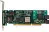
Connecting Drive Activity LED Indicators Connecting Drive Activity LED Indicators Figure 15, 10, and 11 show the location of LED indicators on the different 9550SX controllers. Figure 15. 8-Port 3ware 9550SX-8LP Serial ATA RAID Controller LED indicators for individual drives on J7 and J8 Overall LED drive status indicator: the last two pins of J7 and J8. The anode is the lower of the two pins and the cathode is the upper. LED connector details J7 is for drives 0, 1, 2, 3 (left to right) J8 is for drives 4, 5, 6, 7 (left to right) Figure 16. 4-Port 3ware 9550SX-4LP Serial ATA RAID Controller LED indicators for individual drives on J7: 0, 1, 2, 3 (left to right) Overall LED drive status indicator: the last two pins of J7. The anode is the lower of the two pins and the cathode is the upper. www.3ware.com 17
-
 1
1 -
2
-
3
-
4
-
5
-
6
-
7
-
8
-
9
-
10
-
11
-
12
-
13
-
14
-
15
-
 16
16 -
 17
17 -
 18
18 -
 19
19 -
 20
20 -
 21
21 -
 22
22 -
 23
23 -
 24
24 -
 25
25 -
 26
26 -
27
-
28
-
29
-
30
-
31
-
32
-
33
-
34
-
35
-
36
-
37
-
38
-
39
-
40
 |
 |
