ASRock 4CoreDual-SATA2 R2.0 User Manual
ASRock 4CoreDual-SATA2 R2.0 Manual
 |
View all ASRock 4CoreDual-SATA2 R2.0 manuals
Add to My Manuals
Save this manual to your list of manuals |
ASRock 4CoreDual-SATA2 R2.0 manual content summary:
- ASRock 4CoreDual-SATA2 R2.0 | User Manual - Page 1
4CoreDual-SATA2 User Manual Version 2.0 Published November 2007 Copyright©2007 ASRock INC. All rights reserved. 1 - ASRock 4CoreDual-SATA2 R2.0 | User Manual - Page 2
of documentation by the purchaser for backup purpose, without written consent of ASRock Inc. Products and corporate names appearing in this manual may or may not be , USA ONLY The Lithium battery adopted on this motherboard contains Perchlorate, a toxic substance controlled in Perchlorate - ASRock 4CoreDual-SATA2 R2.0 | User Manual - Page 3
Contents 5 1.2 Specifications 6 1.3 Minimum Hardware Requirement Table for Windows® VistaTM Premium 2007 and Basic OS 9 1.4 Supported PCI Express VGA Card List for PCI Express Graphics Slot 10 1.5 Motherboard Layout 11 1.6 ASRock 6CH Premium I/O Panel 12 2. Installation 13 2.1 Screw Holes - ASRock 4CoreDual-SATA2 R2.0 | User Manual - Page 4
34 3.1.1 BIOS Menu Bar 34 3.1.2 Navigation Keys 35 3.2 Main Screen 35 3.3 Advanced Screen 36 3.3.1 CPU Configuration 36 Exit Screen 50 4. Software Support 51 4.1 Install Operating System 51 4.2 Support CD Information 51 4.2.1 Running Support CD 51 4.2.2 Drivers Menu 51 4.2.3 Utilities - ASRock 4CoreDual-SATA2 R2.0 | User Manual - Page 5
guide to BIOS setup and information of the Support CD. Because the motherboard specifications and the BIOS software might be updated, the content of this manual will be subject to change without notice. In case any modifications of this manual occur, the updated version will be available on ASRock - ASRock 4CoreDual-SATA2 R2.0 | User Manual - Page 6
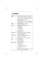
processors (see CAUTION 1) - FSB 1066/800/533 MHz - Supports Hyper-Threading Technology (see CAUTION 2) - Supports Untied Overclocking Technology (see CAUTION 3) - Supports EM64T CPU - Northbridge: VIA® PT880 Pro/PT880 Ultra - Southbridge: VIA® VT8237S - Dual Channel DDR/DDR2 Memory Technology - ASRock 4CoreDual-SATA2 R2.0 | User Manual - Page 7
0Gb/s connectors, support RAID (RAID 0, RAID 1, and JBOD) and "Hot Plug" functions (see CAUTION 10) - 2 x ATA133 IDE connectors (support 4 x IDE devices) - 1 x Floppy connector - 1 x IR header - 1 x Game header - 1 x HDMI_SPDIF header - CPU/Chassis FAN connector - 20 pin ATX power connector - 4 pin - ASRock 4CoreDual-SATA2 R2.0 | User Manual - Page 8
This motherboard supports Untied Overclocking Technology. Please read "Untied Overclocking Technology" on page 33 for details. 4. This motherboard supports Dual Channel Memory Technology. Before you implement Dual Channel Memory Technology, make sure to read the installation guide of memory modules - ASRock 4CoreDual-SATA2 R2.0 | User Manual - Page 9
Basic OS This motherboard can support all features in Windows® VistaTM Premium 2007. Please follow below table for minimum hardware requirement. CPU Memory VGA Celeron D 326 1GB system memory (Premium) 512MB Single Channel (Basic) DX9.0 with WDDM Driver with 128bit VGA memory (Premium) with 64bit - ASRock 4CoreDual-SATA2 R2.0 | User Manual - Page 10
1.4 Supported PCI Express VGA Card List for PCI Express Graphics Slot (for Windows® 2000/XP/XP 64-bit/VistaTM/VistaTM updates of the supported PCI Express VGA card list for PCI Express Graphics slot, please visit ASRock website for details. ASRock website: http://www.asrock.com/support/index.htm 10 - ASRock 4CoreDual-SATA2 R2.0 | User Manual - Page 11
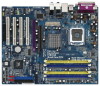
Conroe VIA PT880 Pro / PT880 Ultra Chipset AGP 8X 1.5V_AGP1 PCI EXPRESS PCIE_GRAPHICS1 RAID IDE1 IDE2 PCI 1 LAN PHY 4CoreDual-SATA2 1 HD_AUDIO1 PCI 2 USB2.0 PCI 3 CMOS Battery CLRCMOS1 Audio CODEC HDMI_SPDIF1 GAME1 1 1 PCI 4 RoHS FLOPPY1 USB67 1 USB45 1 VIA VT8237S 4Mb BIOS - ASRock 4CoreDual-SATA2 R2.0 | User Manual - Page 12
ASRock 6CH Premium I/O Panel 1 2 5 3 6 4 7 12 11 10 9 8 1 Parallel Port 2 RJ-45 Port 3 Rear Speaker (Black) 4 Central / Bass (Orange) 5 Line In (Light Blue) * 6 Front Speaker (Lime) 7 Microphone (Pink) 8 USB 2.0 Ports (USB01) 9 USB 2.0 Ports (USB23) 10 Streaming. For Windows® XP: - ASRock 4CoreDual-SATA2 R2.0 | User Manual - Page 13
Chapter 2 Installation 4CoreDual-SATA2 is an ATX form factor (12.0" x 9.6", 30.5 x 24.4 cm) motherboard. Before you install the motherboard, study the configuration of your chassis to ensure that the motherboard fits into it. Make sure to unplug the power cord before installing or removing the - ASRock 4CoreDual-SATA2 R2.0 | User Manual - Page 14
2.3 775-LAND CPU Installation For the installation of Intel 775-LAND CPU, please follow the steps below. 775-Pin Socket Overview Before you insert the 775-LAND CPU into the socket, please check if the CPU surface is unclean or if there is any bent pin on the socket. Do not force to insert the CPU - ASRock 4CoreDual-SATA2 R2.0 | User Manual - Page 15
CPU is within the socket and properly mated to the orient keys. Step 3. Remove PnP Cap (Pick and Place Cap): Use your left hand index finger and thumb to support PnP cap. 2. This cap must be placed if returning the motherboard for after service. Step 4. Close the socket: Step 4-1. Rotate the load - ASRock 4CoreDual-SATA2 R2.0 | User Manual - Page 16
Heatsink This motherboard is equipped with 775-Pin socket that supports Intel 775-LAND CPU. Please adopt the type of heatsink and cooling fan compliant with Intel 775-LAND CPU to dissipate heat. Before you installed the heatsink, you need to spray thermal interface material between the CPU and the - ASRock 4CoreDual-SATA2 R2.0 | User Manual - Page 17
2.5 Installation of Memory Modules (DIMM) 4CoreDual-SATA2 motherboard provides two 184-pin DDR (Double Data Rate) DIMM slots and two 240-pin DDR2 DIMM slots, and supports Dual Channel Memory Technology. For dual channel configuration, you always need to install identical (the same brand, speed, size - ASRock 4CoreDual-SATA2 R2.0 | User Manual - Page 18
Installing a DIMM Please make sure to disconnect power supply before adding or removing DIMMs or the system break The DIMM only fits in one correct orientation. It will cause permanent damage to the motherboard and the DIMM if you force the DIMM into the slot at incorrect orientation. Step - ASRock 4CoreDual-SATA2 R2.0 | User Manual - Page 19
slot of this motherboard! It may cause permanent damage! For the voltage information of your AGP card, please check with the AGP card vendors. PCI Express Graphics slot: PCI Express Graphics slot is used to install PCI Express expansion cards. For the information of the compatible PCI Express VGA - ASRock 4CoreDual-SATA2 R2.0 | User Manual - Page 20
ASRock patented PCI Express Graphics Technology, this motherboard supports Surround Display upgrade. With the external add-on AGP VGA card and PCI Express VGA card, you can easily enjoy the benefits of Surround Display feature. For the detailed instruction current provided by power supply. Clear - ASRock 4CoreDual-SATA2 R2.0 | User Manual - Page 21
motherboard, please set the IDE device as "Master". Please refer to the instruction of your IDE device vendor for the details. Besides, to optimize compatibility see p.11, No. 12) (SATA2: see p.11, No. 11) SATA1 SATA2 These two Serial ATAII (SATAII) connectors support SATAII or SATA hard disk for - ASRock 4CoreDual-SATA2 R2.0 | User Manual - Page 22
2.0 headers on this motherboard. Each USB 2.0 header can support two USB 2.0 ports. This header supports an optional wireless transmitting supports Jack Sensing, but the panel wire on the chassis must support HDA to function correctly. Please follow the instruction in our manual and chassis manual - ASRock 4CoreDual-SATA2 R2.0 | User Manual - Page 23
BIOS Setup Utility. Enter Advanced Settings, and then select Chipset Configuration. Set the Front Panel Control option from [Auto] to [Enabled]. F. Enter Windows black wire to the ground pin. CPU Fan Connector (4-pin CPU_FAN1) (see p.11, No. 5) Please connect the CPU fan 1 GND cable to this - ASRock 4CoreDual-SATA2 R2.0 | User Manual - Page 24
speed control function. If you plan to connect the 3-Pin CPU fan to the CPU fan connector on this motherboard, please connect it to Pin 1-3. Pin 1-3 Connected 3-Pin Fan Installation Game Connector (15-pin GAME1) (see p.11, No. 22) ATX Power Connector (20-pin ATXPWR1) (see p.11, No. 29) +5V JBB1 - ASRock 4CoreDual-SATA2 R2.0 | User Manual - Page 25
HDMI_SPDIF Cable Please connect the black end (A) (Optional) C B A of HDMI_SPDIF cable to the HDMI_SPDIF header on the motherboard. Then connect the white end (B or C) of HDMI_SPDIF cable to the a HDMI_SPDIF connector of HDMI VGA card. A. black end +5V SPDIFOUT GND blue black B. white - ASRock 4CoreDual-SATA2 R2.0 | User Manual - Page 26
2.10 HDMI_SPDIF Header Connection Guide HDMI (High-Definition Multi-media Interface) is an all-digital audio/video specification, which provides an interface between any compatible digital audio/ video source, such as a set-top box, DVD player, A/V receiver and a compatible digital audio or video - ASRock 4CoreDual-SATA2 R2.0 | User Manual - Page 27
guide. Some default setting of SATAII hard disks may not be at SATAII mode, which operate with the best performance. In order to enable SATAII function, please follow the below instruction 's website for details: http://www.hitachigst.com/hdd/support/download.htm The above examples are just for your - ASRock 4CoreDual-SATA2 R2.0 | User Manual - Page 28
adopts VIA® VT8237S southbridge chipset that supports Serial ATA (SATA) / Serial ATAII (SATAII) hard disks and RAID (RAID 0, RAID 1, and JBOD) functions. You may install SATA / SATAII hard disks on this motherboard for internal storage devices. This section will guide you to install the SATA - ASRock 4CoreDual-SATA2 R2.0 | User Manual - Page 29
is installed into system properly. The latest SATA / SATAII driver is available on our support website: www.asrock.com 4. Make sure to use the SATA power cable & data cable, which are from our motherboard package. 5. Please follow below instructions step by step to reduce the risk of HDD crash or - ASRock 4CoreDual-SATA2 R2.0 | User Manual - Page 30
instruction sequence to process the Hot Plug, improper procedure will cause the SATA / SATAII HDD damage and data loss. Step 1 Please connect SATA power cable 1x4-pin end Step 2 Connect SATA data cable to (White) to the power supply 1x4-pin cable. the motherboard's SATAII connector. SATA power - ASRock 4CoreDual-SATA2 R2.0 | User Manual - Page 31
system is power on and in working condition. As soon as the RAID driver with Hot Swap function under RAID 1 is ready, we will upload it to our website. Please visit our website for RAID driver update in the near future. ASRock website: http://www.asrock.com 2.16.1 Installing Windows® 2000 / XP - ASRock 4CoreDual-SATA2 R2.0 | User Manual - Page 32
part of the document in the following path in the Support CD: .. \ RAID Installation Guide 2. If you want to use "VIA RAID Tool" in Windows® environment, please install SATA / SATAII drivers from the Support CD again so that "VIA RAID Tool" will be installed to your system as well. 2.16.2 Installing - ASRock 4CoreDual-SATA2 R2.0 | User Manual - Page 33
/ Windows® VistaTM / Windows® VistaTM 64-bit OS on your system. 2.18 Untied Overclocking Technology This motherboard supports Untied Overclocking Technology, which means during overclocking, FSB enjoys better margin due to fixed AGP / PCI / PCIE bus. You may set "CPU Host Frequency" option of BIOS - ASRock 4CoreDual-SATA2 R2.0 | User Manual - Page 34
Memory on the motherboard stores the BIOS SETUP UTILITY. You may run the BIOS SETUP UTILITY when you start up the computer. Please press during the Power-On-Self-Test (POST) to enter the BIOS on. Because the BIOS software is constantly being updated, the following BIOS setup screens and - ASRock 4CoreDual-SATA2 R2.0 | User Manual - Page 35
:00:09] [Wed 11/21/2007] BIOS Version : 4CoreDual-SATA2 BIOS P1.70 Processor Type : Intel (R) CPU 3.60 GHz (64bit) Processor Speed : 3600 MHz Microcode Update : F43/4 Cache Size : 1024KB Total Memory DDRII 1 DRD 1 DDRII 2 DDR 2 : 512MB Dual-Channel Memory Mode : None : 256MB/166MHz (DDR333 - ASRock 4CoreDual-SATA2 R2.0 | User Manual - Page 36
24, Min: 14) Ratio Actual Value 24 Ratio CMOS Setting [24] Max CPUID Value Limit Intel (R) Virtualization tech. No-Excute Memory Protection Hyper Threading Technology [Disabled] [Enabled] [Disabled] [Enabled] Select how to set the CPU host frequency. +F1 F9 F10 ESC Select Screen Select Item - ASRock 4CoreDual-SATA2 R2.0 | User Manual - Page 37
the ratio value of this motherboard. Max CPUID Value Limit For Prescott CPU only, some OSes (ex. NT4.0) cannot handle the function with disable. This should be enabled in order to boot legacy OSes that cannot support CPUs with extended CPUID functions. Intel (R) Virtualization tech. When this option - ASRock 4CoreDual-SATA2 R2.0 | User Manual - Page 38
BIOS [Auto] [Auto] [Auto] [Auto] [2T Command] DRAM Voltage AGP Voltage [Auto] [Auto] Options 133MHz 166MHz 200MHz Auto (DDR266) ( ] is selected, the motherboard will detect the memory module(s) inserted and assigns tolerance for memory compatibility when it is set to [Enabled]. DRAM CAS# Latency - ASRock 4CoreDual-SATA2 R2.0 | User Manual - Page 39
] and [Dual Channel] if you have properly set the dual channel memory configuration. DRAM Command Rate Use this to select among [2T Command] [Low] for DRAM Voltage. The default value is [Auto]. AGP Voltage Use this to select among [Auto], [Normal] and [High] for AGP Voltage. The default value is - ASRock 4CoreDual-SATA2 R2.0 | User Manual - Page 40
an 8X-AGP card on this motherboard, you may select [Auto], support. AGP Aperture Size It refers to a section of the PCI memory address range used for graphics memory and South Bridge V-Link Speed of VIA chipset. configuration options: [Normal], [ the PCI Bus when the CPU is accessing 8-bit ISA cards - ASRock 4CoreDual-SATA2 R2.0 | User Manual - Page 41
-RAM feature. Select [Auto] will enable this feature if the system supports it. Restore on AC/Power Loss This allows you to set the power state after an unexpected AC/Power loss. If [Power Off] is selected, the AC/Power remains off when the power recovers. If [Power On] is selected, the AC/Power - ASRock 4CoreDual-SATA2 R2.0 | User Manual - Page 42
RAID]. If you want to operate RAID function on SATA HDDs, please select [RAID instruction, which can be applied to the configurations of "Primary IDE Slave", "Secondary IDE Master", and "Secondary IDE Slave" as well. BIOS .0 GB :Supported :16Sectors :4 :MultiWord DMA-2 :Ultra DMA-5 :Supported [Auto] - ASRock 4CoreDual-SATA2 R2.0 | User Manual - Page 43
hard disk drive. After selecting the hard disk information into BIOS, use a disk utility, such as FDISK, to partition and mode for a hard disk > 512 MB under DOS and Windows; for Netware and UNIX user, select [Disabled] to disable speed and data-integrity for compatible IDE devices. S.M.A.R.T. Use - ASRock 4CoreDual-SATA2 R2.0 | User Manual - Page 44
item to enable or disable the PCI IDE BusMaster feature. 3.3.6 Floppy Configuration In this section, you may configure the type of your floppy drive. BIOS SETUP UTILITY Advanced Floppy Configuration Floppy A [1.44 MB 312"] Select the type of floppy drive connected to the system. +F1 F9 F10 ESC - ASRock 4CoreDual-SATA2 R2.0 | User Manual - Page 45
Channel Parallel Port IRQ OnBoard Game Port OnBoard MIDI Port [Enabled] [3F8 / IRQ4] [Disabled] [378] [ECP + EPP] [1.9] [DMA3] [IRQ7] [Auto] [Disabled] Allow BIOS to Enable or Disable Floppy Controller. +F1 F9 F10 ESC Select Screen Select Item Change Option General Help Load Defaults Save and - ASRock 4CoreDual-SATA2 R2.0 | User Manual - Page 46
the MIDI Port or disable it. Configuration options: [Disabled], [300], and [330]. 3.3.8 USB Configuration BIOS SETUP UTILITY Advanced USB Configuration USB Controller USB 2.0 Support Legacy USB Support [Enabled] [Enabled] [Disabled] To enable or disable the onboard USB controllers. +F1 F9 F10 - ASRock 4CoreDual-SATA2 R2.0 | User Manual - Page 47
you to monitor the status of the hardware on your system, including the parameters of the CPU temperature, motherboard temperature, CPU fan speed, chassis fan speed, and the critical voltage. BIOS SETUP UTILITY Main Advanced H/W Monitor Boot Security Exit Hardware Health Event Monitoring - ASRock 4CoreDual-SATA2 R2.0 | User Manual - Page 48
, it will display the available devices on your system for you to configure the boot settings and the boot priority. Main Advanced BIOS SETUP UTILITY H/W Monitor Boot Security Exit Boot Settings Boot Settings Configuration 1st Boot Device 2nd Boot Device 3rd Boot Device 4th Boot Device - ASRock 4CoreDual-SATA2 R2.0 | User Manual - Page 49
1985-2003, American Megatrends, Inc. Boot From Onboard LAN Use this item to enable or disable the Boot From Onboard LAN feature. VIA SATA Raid Utility Use this to enable or disable VIA® VT8237S SATA Raid BIOS Utility during POST. This item will be hidden if "SATA Operation Mode" is set to [non - ASRock 4CoreDual-SATA2 R2.0 | User Manual - Page 50
and exit setup?" Select [OK] to save the changes and exit the BIOS SETUP UTILITY. Discard Changes and Exit When you select this option, it message, "Discard changes and exit setup?" Select [OK] to exit the BIOS SETUP UTILITY without saving any changes. Discard Changes When you select this option - ASRock 4CoreDual-SATA2 R2.0 | User Manual - Page 51
install the necessary drivers to activate the devices. 4.2.3 Utilities Menu The Utilities Menu shows the applications software that the motherboard supports. Click on a specific item then follow the installation wizard to install it. 4.2.4 Contact Information If you need to contact ASRock or want to
-
 1
1 -
 2
2 -
 3
3 -
 4
4 -
 5
5 -
 6
6 -
 7
7 -
8
-
9
-
10
-
11
-
12
-
13
-
14
-
15
-
16
-
17
-
18
-
19
-
20
-
21
-
22
-
23
-
24
-
25
-
26
-
27
-
28
-
29
-
30
-
31
-
32
-
33
-
34
-
35
-
36
-
37
-
38
-
39
-
40
-
41
-
42
-
43
-
44
-
45
-
46
-
47
-
48
-
49
-
50
-
51
 |
 |
1
4CoreDual-SATA2
User Manual
Version 2.0
Published November 2007
Copyright©2007 ASRock INC. All rights reserved.