ASRock 775Dual-915GV User Manual
ASRock 775Dual-915GV Manual
 |
View all ASRock 775Dual-915GV manuals
Add to My Manuals
Save this manual to your list of manuals |
ASRock 775Dual-915GV manual content summary:
- ASRock 775Dual-915GV | User Manual - Page 1
775Dual-915GV User Manual Version 1.0 Published August 2005 Copyright©2005 ASRock INC. All rights reserved. 1 - ASRock 775Dual-915GV | User Manual - Page 2
no responsibility for any errors or omissions that may appear in this manual. With respect to the contents of this manual, ASRock does not provide warranty of any kind, either expressed or implied, including but not limited to the implied warranties or conditions of merchantability or fitness - ASRock 775Dual-915GV | User Manual - Page 3
Supported PCI Express VGA Cards Lists for AGI Express Slot (PCI Express x 4 11 1.5 Motherboard Layout 12 1.6 ASRock 8CH I/O 13 2 Installation 14 2.1 Screw Holes 14 2.2 Pre-installation Precautions 14 2.3 CPU Installation 15 2.4 Installation of Heatsink and CPU fan 3.3.2 Chipset Configuration - ASRock 775Dual-915GV | User Manual - Page 4
4 Software Support 42 4.1 Install Operating System 42 4.2 Support CD Information 42 4.2.1 Running Support CD 42 4.2.2 Drivers Menu 42 4.2.3 Utilities Menu 42 4.2.4 "LGA 775 CPU Installation Live Demo" Program .. 42 4.2.5 Contact Information 42 4 - ASRock 775Dual-915GV | User Manual - Page 5
and CPU support lists on ASRock website as well. ASRock website http://www.asrock.com 1.1 Package Contents ASRock 775Dual-915GV Motherboard (Micro ATX Form Factor: 9.6-in x 9.6-in, 24.4 cm x 24.4 cm) ASRock 775Dual-915GV Quick Installation Guide ASRock 775Dual-915GV Support CD (including LGA 775 CPU - ASRock 775Dual-915GV | User Manual - Page 6
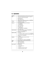
in, 24.4 cm x 24.4 cm - 775-Pin Socket supporting Intel® Pentium® 4 / Celeron® D processor (in 775-land LGA package) - FSB 800/533 MHz - Supports EM64T CPU - Supports Hyper-Threading Technology (see CAUTION 1) - Northbridge: Intel® 915GV chipset - Southbridge: Intel® ICH6 - Dual Channel DDR/DDRII - ASRock 775Dual-915GV | User Manual - Page 7
jumperfree - SMBIOS 2.3.1 Support - Drivers, Utilities, AntiVirus Software - CPU Temperature Sensing - Chassis Temperature Sensing - CPU Overheat Shutdown to Protect CPU Life - CPU Fan Tachometer - Chassis Fan Tachometer - Voltage Monitoring: +12V, +5V, +3.3V, Vcore - Microsoft® Windows® 2000 / XP - ASRock 775Dual-915GV | User Manual - Page 8
fan on the motherboard Express VGA card, please refer to the installation guide on page 20. 8. The Max. shared memory of onboard VGA is controlled by Intel VGA driver. Installing different Intel VGA driver may vary its Max. shared memory capacity. 9. For microphone input, this motherboard supports - ASRock 775Dual-915GV | User Manual - Page 9
(for Windows 2000/Windows XP) I. AGP 4X Graphics Chip Vendor n-VIDIA ATI Model Name ASUS V8170 Ennyah G2 MX400 POWERCOLOR Radeon 9100 Chipset Name GeForce MX440SE GeForce 2 MX400 Radeon 9100 For the latest updates of the supported AGP VGA card list for AGI slot, please visit ASRock website for - ASRock 775Dual-915GV | User Manual - Page 10
II. AGP 8X Graphics Chip Model Name Chipset Name Vendor n-VIDIA ASUS V9480 GeForce 4 Ti4800SE ASUS 9250 For the latest updates of the supported AGP VGA card list for AGI slot, please visit ASRock website for details. ASRock website: http://www.asrock.com/support/index.htm Note. ATi 9600, 9550 - ASRock 775Dual-915GV | User Manual - Page 11
GV-RX60P128D MSI X800XT POWERCOLOR X300 SE Chipset Name GeForce PCX5900 GeForce 6200 GeForce supported PCI Express VGA card list for AGI Express slot (PCI Express x 4), please visit ASRock website for details. ASRock website: http://www.asrock.com/support/index.htm Note. Turbo cache PCI Express - ASRock 775Dual-915GV | User Manual - Page 12
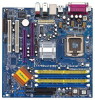
Motherboard ATXPWR1 ` Intel 915GV Chipset AGI_EXPRESS1 PCI EXPRESS 775Dual-915GV Dual Channel 1 PS2_USB_PWR1 Jumper 2 ATX 12V Connector (ATX12V1) 3 775-Pin CPU Socket 4 CPU Fan Connector (CPU_FAN1) 5 2 x 240-pin DDRII DIMM 21 North Bridge Controller 22 ASRock Graphics Interface Slot (AGI) - ASRock 775Dual-915GV | User Manual - Page 13
1.6 ASRock 8CH I/O 1 2 3 6 4 7 5 8 13 12 11 10 1 Parallel Port 2 RJ-45 Port 3 Side Speaker (Gray) 4 Rear Speaker (Black) 5 Central / Bass (Orange) 6 Line In (Light Blue) *7 Front Speaker ( - ASRock 775Dual-915GV | User Manual - Page 14
2 Installation 775Dual-915GV is a Micro ATX form factor (9.6" x 9.6", 24.4 x 24.4 cm) motherboard. Before you install the motherboard, study the configuration of your chassis to ensure that the motherboard fits into it. Make sure to unplug the power cord before installing or removing the motherboard - ASRock 775Dual-915GV | User Manual - Page 15
For the installation of Intel 775-LAND CPU, please follow the steps below. 775-Pin Socket Overview Before you insert the 775-LAND CPU into the load plate to fully open position at approximately 100 degrees. Step 2. Insert the 775-LAND CPU: Step 2-1. Hold the CPU by the edges where are marked with - ASRock 775Dual-915GV | User Manual - Page 16
Pick and Place Cap): Use your left hand index finger and thumb to support the load plate edge, engage PnP cap with right hand thumb and peel off the PnP cap. 2. This cap must be placed if returning the motherboard for after service. Step 4. Close the socket: Step 4-1. Rotate the load plate onto the - ASRock 775Dual-915GV | User Manual - Page 17
Fan and Heatsink This motherboard is equipped with 775-Pin socket that supports Intel 775-LAND CPU. Please adopt the type of heatsink and cooling fan compliant with Intel 775 instruction manuals of your CPU fan and heatsink. Below is an example to illustrate the installation of the heatsink for 775- - ASRock 775Dual-915GV | User Manual - Page 18
of Memory Modules (DIMM) 775Dual-915GV motherboard provides two 184-pin DDR (Double Data Rate) DIMM slots and two 240-pin DDRII DIMM slots, and supports Dual Channel Memory Technology. For dual channel configuration, you always need to install identical (the same brand, speed, size and chip-type - ASRock 775Dual-915GV | User Manual - Page 19
matches the break on the slot. notch break notch break The DIMM only fits in one correct orientation. It will cause permanent damage to the motherboard and the DIMM if you force the DIMM into the slot at incorrect orientation. Step 3. Firmly insert the DIMM into the slot until the retaining - ASRock 775Dual-915GV | User Manual - Page 20
the add-on AGP VGA card or PCI Express VGA card, BIOS setup will automatically disable the onboard VGA. 2. Please make sure to set the BIOS onboard VGA selection into "En abled" if you want this motherboard to support Surround Display. Then the onboard VGA in Windows will be the primary VGA card - ASRock 775Dual-915GV | User Manual - Page 21
and PCI Express VGA card, you can easily enjoy the benefits of Surround Display feature. Please make sure to set the BIOS onboard VGA selection into "Enabled", and start your computer with onboard VGA if you want this motherboard to support multi-monitors. For the detailed instruction, please refer - ASRock 775Dual-915GV | User Manual - Page 22
) (39-pin IDE1, see p.12 No. 9) PIN1 IDE1 connect the blue end connect the black end to the motherboard to the IDE devices 80-conductor ATA 66/100 cable Note: Please refer to the instruction of your IDE device vendor for the details. Serial ATA Connectors (SATA1: see p.12 No. 14) (SATA2 - ASRock 775Dual-915GV | User Manual - Page 23
on the I/O panel are not sufficient, this USB 2.0 header is available to support 2 additional USB 2.0 ports. USB 2.0 Header (9-pin USB45) (see p.12 No. 15) USB_PWR P-5 P+5 GND DUMMY 1 GND P+4 P-4 USB_PWR ASRock 8CH I/O accommodates 4 default USB 2.0 ports. If those USB 2.0 ports on the I/O panel - ASRock 775Dual-915GV | User Manual - Page 24
Speaker Header (4-pin SPEAKER 1) (see p.12 No. 18) Chassis Fan Connector (3-pin CHA_FAN1) (see p.12 No. 17) CPU Fan Connector (4-pin CPU_FAN1) (see p.12 No. 4) ATX Power Connector COM port header is used to support a COM port module. Please connect an ATX 12V power supply to this connector. 24 - ASRock 775Dual-915GV | User Manual - Page 25
2.10 Serial ATA (SATA) Hard Disks Installation This motherboard adopts Intel ICH6 south bridge chipset that supports Serial ATA (SATA) hard disks. You may install SATA hard disks on this motherboard for internal storage devices. This section will guide you to install the SATA hard disks. STEP 1: - ASRock 775Dual-915GV | User Manual - Page 26
Chapter 3 BIOS SETUP UTILITY 3.1 Introduction This section explains how to use the BIOS SETUP UTILITY to configure your system. The BIOS FWH chip on the motherboard stores the BIOS SETUP UTILITY. You may run the BIOS SETUP UTILITY when you start up the computer. Please press during the Power-On - ASRock 775Dual-915GV | User Manual - Page 27
System Overview System Time System Date [14:00:09] [Thu 08/04/2005] BIOS Version : 775Dual-915GV BIOS P1.00 Processor Type : Intel (R) CPU 3.60 Ghz (64bit supported) Processor Speed : 3600 MHz Microcode Update : F43/4 Cache Size : 2048KB Total Memory DDRII 1 DDRII 2 : 256MB with 8MB - ASRock 775Dual-915GV | User Manual - Page 28
CPU Configuration Chipset Configuration ACPI Technology Max CPUID Value Limit No-Excute Memory Protection Enhance Halt State Intel (R) SpeedStep(tm) tech. [Auto] [200] [Enabled] [ BIOS auto detects the present CPU host frequency of this motherboard. The actual CPU host frequency will show in the - ASRock 775Dual-915GV | User Manual - Page 29
C1 state is supported through the native processor instructions HLT and MWAIT and requires no hardware support from the chipset. In the C1 power state, the processor maintains the context of the system caches. Intel (R) SpeedStep(tm) tech. Intel (R) SpeedStep(tm) tech. is Intel's new power saving - ASRock 775Dual-915GV | User Manual - Page 30
Configuration BIOS SETUP UTILITY Advanced Chipset Configuration DRAM Frequency [Auto] Flexibility Option [Disabled] , American Megatrends, Inc. DRAM Frequency If [Auto] is selected, the motherboard will detect the memory module(s) inserted and assigns appropriate frequency automatically. You - ASRock 775Dual-915GV | User Manual - Page 31
onboard VGA will be automatically disabled when you install AGP 8X or PCI Express X 16 VGA card; the onboard VGA will be enabled without the installation of onboard VGA. No matter you insert DDR or DDRII DIMM to this motherboard, you may select [256MB] or [128MB] as the aperture size select. - ASRock 775Dual-915GV | User Manual - Page 32
3.3.3 ACPI Configuration BIOS SETUP UTILITY Advanced ACPI Configuration Suspend To RAM Restore on AC/Power Loss Ring-In Power On PCI Devices Power On PS / 2 Keyboard Power On RTC Alarm Power On [Disabled] [Power Off] [Disabled] [Disabled] [Disabled] [Disabled] Select auto-detect or disable the - ASRock 775Dual-915GV | User Manual - Page 33
not work. Likewise, if it is set to [IDE 1, SATA 2, SATA 4], then SATA1, SATA3 will not work. Because Intel® ICH6 south bridge only supports four IDE devices under legacy OS (Windows NT), you have to choose [SATA 1, SATA 2, SATA 3, SATA 4], [SATA 1, SATA 3, IDE 1], or [IDE 1, SATA 2, SATA 4] when - ASRock 775Dual-915GV | User Manual - Page 34
Mode S.M.A.R.T. 32Bit Data Transfer :Hard Disk :ST340014A :40.0 GB :Supported :16Sectors :4 :MultiWord DMA-2 :Ultra DMA-5 :Supported [Auto] [Auto] [Auto] [Auto] [Auto] [Disabled] [ disk > 512 MB under DOS and Windows; for Netware and UNIX user, select [Disabled] to disable the LBA/Large mode. 34 - ASRock 775Dual-915GV | User Manual - Page 35
PIO mode to enhance hard disk performance by optimizing the hard disk timing. DMA Mode DMA capability allows the improved transfer-speed and data-integrity for compatible IDE devices. S.M.A.R.T. Use this item to enable or disable the S.M.A.R.T. (Self-Monitoring, Analysis, and Reporting Technology - ASRock 775Dual-915GV | User Manual - Page 36
Exit Exit v02.54 (C) Copyright 1985-2005, American Megatrends, Inc. 3.3.7 Super IO Configuration BIOS SETUP UTILITY Advanced Configure Super IO Chipset OnBoard Floppy Controller Serial Port Address Infrared Port Address Parallel Port Address Parallel Port Mode EPP Version ECP Mode DMA Channel - ASRock 775Dual-915GV | User Manual - Page 37
Parallel Port Address Use this item to set the address for the onboard parallel port or disable it. Configuration options: [Disabled], [378], and [278]. Parallel Port Mode Use this item to set the operation mode of the parallel port. The default value is [ECP+EPP]. If this option is set to [ECP+EPP - ASRock 775Dual-915GV | User Manual - Page 38
will disable the legacy USB support. 3.4 Hardware Health Event Monitoring Screen In this section, it allows you to monitor the status of the hardware on your system, including the parameters of the CPU temperature, motherboard temperature, CPU fan speed, chassis fan speed, and the critical voltage - ASRock 775Dual-915GV | User Manual - Page 39
3.5 Boot Screen In this section, it will display the available devices on your system for you to configure the boot settings and the boot priority. Main Advanced BIOS SETUP UTILITY H/W Monitor Boot Security Exit Boot Settings Boot Settings Configuration Configure Settings during System Boot. - ASRock 775Dual-915GV | User Manual - Page 40
3.6 Security Screen In this section, you may set or change the supervisor/user password for the system. For the user password, you may also clear it. BIOS SETUP UTILITY Main Advanced H/W Monitor Boot Security Exit Security Settings Supervisor Password : Not Installed User Password : Not - ASRock 775Dual-915GV | User Manual - Page 41
3.7 Exit Screen Main BIOS SETUP UTILITY Advanced H/W Monitro Boot Security Exit Exit Options Save Changes and Exit Discard Changes and Exit Discard Changes Load Optimal Defaults Exit system setup after saving the changes. F10 key can be used for this operation. Select Screen Select Item - ASRock 775Dual-915GV | User Manual - Page 42
Live Demo" Program This motherboard is equipped with Intel LGA 775 socket, which is a new CPU socket interface that Intel has released. Since it has several tiny pins, whcih are easily to be damaged by improper handling, ASRock sincerely presents you a clear installation guide through this "LGA
-
 1
1 -
 2
2 -
 3
3 -
 4
4 -
 5
5 -
 6
6 -
 7
7 -
8
-
9
-
10
-
11
-
12
-
13
-
14
-
15
-
16
-
17
-
18
-
19
-
20
-
21
-
22
-
23
-
24
-
25
-
26
-
27
-
28
-
29
-
30
-
31
-
32
-
33
-
34
-
35
-
36
-
37
-
38
-
39
-
40
-
41
-
42
 |
 |

1
775Dual-915GV
User Manual
Version 1.0
Published August 2005
Copyright©2005 ASRock INC. All rights reserved.