ASRock 775i65PE Quick Installation Guide
ASRock 775i65PE Manual
 |
View all ASRock 775i65PE manuals
Add to My Manuals
Save this manual to your list of manuals |
ASRock 775i65PE manual content summary:
- ASRock 775i65PE | Quick Installation Guide - Page 1
for backup purpose, without written consent of ASRock Inc. Products and corporate names appearing in this guide may or may not be registered trademarks or ASRock Website: http://www.asrock.com Published October 2004 Copyright©2004 ASRock INC. All rights reserved. 1 ASRock 775i65PE Motherboard - ASRock 775i65PE | Quick Installation Guide - Page 2
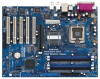
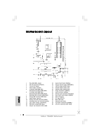
(FLOPPY1) 21 Game Connector (GAME1) 22 Internal Audio Connector: CD1 (Black) 23 Front Panel Audio Header (AUDIO1) 24 JR1 / JL1 Jumpers 25 PCI Slots (PCI1- 5) 26 BIOS FWH Chip 27 AGP Slot (1.5V_AGP1) 28 ATX Power Connector (ATXPWR1) 29 CPU Fan Connector (CPU_FAN1) 2 ASRock 775i65PE Motherboard - ASRock 775i65PE | Quick Installation Guide - Page 3
details in accordance with the type of speaker you use. TABLE for Audio Output Connection Audio Output Channels Front Speaker Rear Speaker Central / Bass (No. 7) (No. 4) (No. 5) 2 V -- -- 4 V V -- 6 V V V 8 V V V Side Speaker (No. 3) ---V 3 ASRock 775i65PE Motherboard English - ASRock 775i65PE | Quick Installation Guide - Page 4
memory and CPU support lists on ASRock website as well. ASRock website http://www.asrock.com 1.1 Package Contents ASRock 775i65PE Motherboard (ATX Form Factor: 12.0-in x 9.0-in, 30.5 cm x 22.9 cm) ASRock 775i65PE Quick Installation Guide ASRock 775i65PE Support CD (including LGA 775 CPU Installation - ASRock 775i65PE | Quick Installation Guide - Page 5
x 9.0-in, 30.5 cm x 22.9 cm CPU: 775-Pin Socket Supporting Intel® Pentium® 4 / Celeron® processor (in 775-land LGA package) Chipsets: North Bridge: Intel® 865PE chipset, FSB @ 800 / 533MHz, Max. 1066 MHz at overclocking mode (see CAUTION 1), supports Hyper-Threading Technology (see CAUTION - ASRock 775i65PE | Quick Installation Guide - Page 6
® Windows® 98/ ME. 8. For microphone input, this motherboard supports both stereo and mono modes. For audio output, this motherboard supports 2-channel, 4-channel, 6-channel, and 8-channel modes. Please check the table on page 3 for proper connection. 6 ASRock 775i65PE Motherboard English - ASRock 775i65PE | Quick Installation Guide - Page 7
Before you insert the 775-LAND CPU into the socket, please check if the CPU surface is unclean or if there is any bent pin on the socket. Do not force to insert the CPU into the socket if above situation is found. Otherwise, the CPU will be seriously damaged. 7 ASRock 775i65PE Motherboard English - ASRock 775i65PE | Quick Installation Guide - Page 8
100 degrees. Step 2. Insert the 775-LAND CPU: Step 2-1. Hold the CPU by the edges where are marked with support the load plate edge, engage PnP cap with right hand thumb and peel the cap from the socket while pressing on center of PnP cap to assist in removal. 8 ASRock 775i65PE Motherboard - ASRock 775i65PE | Quick Installation Guide - Page 9
installation, please kindly refer to the instruction manuals of your CPU fan and heatsink. Below is an example to illustrate the installation of the heatsink for 775-LAND CPU. Step 1. Apply thermal interface material onto center of IHS on the socket surface. Step 2. Step 3. Step 4. Place the - ASRock 775i65PE | Quick Installation Guide - Page 10
2.3 Installation of Memory Modules (DIMM) 775i65PE motherboard provides four 184-pin DDR (Double Data Rate) DIMM slots, and supports Dual Channel Memory Technology. For dual channel configuration, you unable to activate the Dual Channel Memory Technology. English 10 ASRock 775i65PE Motherboard - ASRock 775i65PE | Quick Installation Guide - Page 11
permanent damage to the motherboard and the DIMM if you force the DIMM into the slot at incorrect orientation. STEP 3: Firmly insert the DIMM into the slot until the retaining clips at both ends fully snap back in place and the DIMM is properly seated. 11 ASRock 775i65PE Motherboard English - ASRock 775i65PE | Quick Installation Guide - Page 12
firmly until the card is completely seated on the slot. STEP 5: Fasten the card to the chassis with screws. STEP 6: Replace the system cover. 12 ASRock 775i65PE Motherboard English - ASRock 775i65PE | Quick Installation Guide - Page 13
jumpers JL1 and JR1 are short, both the front panel and the rear panel audio connectors can work. Clear CMOS (CLRCMOS0, 2-pin jumper) (see p.2 No. updating the BIOS, you must boot up the system first, and then shut it down before you do the clear-CMOS action. English 13 ASRock 775i65PE Motherboard - ASRock 775i65PE | Quick Installation Guide - Page 14
connectors support SATA data cables for internal storage devices. The current SATA interface allows up to 1.5 Gb/s data transfer rate. Serial ATA (SATA) Data Cable Either end of the SATA data cable can be connected to the SATA hard disk or the SATA connector on the motherboard. 14 ASRock 775i65PE - ASRock 775i65PE | Quick Installation Guide - Page 15
audio input from sound sources such as a CD-ROM, DVD-ROM, TV tuner card, or MPEG card. Front Panel Audio Header (9-pin AUDIO1) (see p.2 No. 23) This is an interface for front panel audio cable that allows convenient connection and control of audio devices. English 15 ASRock 775i65PE Motherboard - ASRock 775i65PE | Quick Installation Guide - Page 16
connect a chassis fan cable to this connector and match the black wire to the ground pin. Please connect a CPU fan cable to this connector and match the black wire to the ground pin. Please connect an ATX power supply to do so will cause the failure to power up. 16 ASRock 775i65PE Motherboard - ASRock 775i65PE | Quick Installation Guide - Page 17
need to check and ensure the configuration of the OnBoard IDE Operate Mode option in BIOS setup is correct according to the condition of your system. For the configuration details, please refer to the instruction on page 28 of "User Manual" in the Support CD. 17 ASRock 775i65PE Motherboard English - ASRock 775i65PE | Quick Installation Guide - Page 18
the BIOS Setup Utility, please refer to the User Manual (PDF file) contained in the Support CD. 4. Software Support CD information This motherboard supports various Microsoft® Windows® operating systems: 98 SE/ ME / 2000 / XP. The Support CD that came with the motherboard contains necessary drivers - ASRock 775i65PE | Quick Installation Guide - Page 19
19 ASRock 775i65PE Motherboard - ASRock 775i65PE | Quick Installation Guide - Page 20
® Intel® ICH5, 20 ASRock 775i65PE Motherboard - ASRock 775i65PE | Quick Installation Guide - Page 21
® ® 21 ASRock 775i65PE Motherboard - ASRock 775i65PE | Quick Installation Guide - Page 22
22 ASRock 775i65PE Motherboard - ASRock 775i65PE | Quick Installation Guide - Page 23
23 ASRock 775i65PE Motherboard - ASRock 775i65PE | Quick Installation Guide - Page 24
24 ASRock 775i65PE Motherboard - ASRock 775i65PE | Quick Installation Guide - Page 25
25 ASRock 775i65PE Motherboard - ASRock 775i65PE | Quick Installation Guide - Page 26
26 ASRock 775i65PE Motherboard - ASRock 775i65PE | Quick Installation Guide - Page 27
27 ASRock 775i65PE Motherboard - ASRock 775i65PE | Quick Installation Guide - Page 28
" " SATA1 SATA2 28 ASRock 775i65PE Motherboard - ASRock 775i65PE | Quick Installation Guide - Page 29
CD1 29 ASRock 775i65PE Motherboard - ASRock 775i65PE | Quick Installation Guide - Page 30
30 ASRock 775i65PE Motherboard - ASRock 775i65PE | Quick Installation Guide - Page 31
31 ASRock 775i65PE Motherboard - ASRock 775i65PE | Quick Installation Guide - Page 32
® ® "LGA 775 CPU Installation Live Demo" 32 ASRock 775i65PE Motherboard - ASRock 775i65PE | Quick Installation Guide - Page 33
auf der Webseite von ASRock. ASRock-Website: http://www.asrock.com 1.1 Kartoninhalt ASRock 775i65PE Motherboard (ATX-Formfaktor: 30.5 cm x 22.9 cm; 12.0 Zoll x 9.0 Zoll) ASRock 775i65PE Schnellinstallationsanleitung ASRock 775i65PE_ Support-CD (einschl. LGA 775 CPU Installation Live-Demo) Ein - ASRock 775i65PE | Quick Installation Guide - Page 34
30.5 cm x 22.9cm; 12.0 Zoll x 9.0 Zoll CPU: Unterstützt 775-Pin Socket für Intel Pentium 4 / Celeron Prozessor (in 775-land LGA Paket) Chipsatz: North Bridge: Intel® 865PE-Chipsatz, Unterstützung 4 zusätzlicher USB 2.0-Anschlüsse (siehe VORSICHT 7) Deutsch 34 ASRock 775i65PE Motherboard - ASRock 775i65PE | Quick Installation Guide - Page 35
wieder ein. Um die Wärmeableitung zu verbessern, bitte nicht vergessen, etwas Wärmeleitpaste zwischen CPU und Kühlkörper zu sprühen. 6. Stecken Sie KEINE 3,3V AGP-Karte in den AGP-Steckplatz dieses Motherboards! Permanente Beschädigung könnte die Folge sein! 35 ASRock 775i65PE Motherboard Deutsch - ASRock 775i65PE | Quick Installation Guide - Page 36
(Sockel) Deutsch 775-Pin Sockel Übersicht Bevor Sie die 775-Pin CPU in den Sockel sitzen, prüfen Sie bitte, ob die CPU-Oberfläche sauber ist und keine der Kontakte verbogen sind. Setzen Sie die CPU nicht mit Gewalt in den Sockel, dies kann die CPU schwer beschädigen. 36 ASRock 775i65PE Motherboard - ASRock 775i65PE | Quick Installation Guide - Page 37
775-Pin Sockel 775-Pin CPU Um die CPU ordnungsgemäß einsetzen zu können, richten Sie die zwei Orientierungskerben der CPU mit den beiden Markierungen des Sockels aus. Schritt 2-3. Drücken Sie die CPU vorsichtig in vertikaler Richtung in den Sockel. 37 ASRock 775i65PE Motherboard - ASRock 775i65PE | Quick Installation Guide - Page 38
Schritt 2-4. Prüfen Sie, dass die CPU ordnungsgemäß im Sockel sitzt und die Orientierungskerben einwandfrei in den entsprechenden Auskerbungen sitzen. en Sie den Ladehebel. Schritt 4-3. Sichern Sie Ladehebel und Ladeplatte mithilfe des Hebelverschlusses. 38 ASRock 775i65PE Motherboard Deutsch - ASRock 775i65PE | Quick Installation Guide - Page 39
nicht ordnungsgemäß am Motherboard befestigt. Schritt 5. Schließen Sie den Lüfter an den CPULüfteranschluss des Motherboards. Schritt 6. Befestigen Sie überschüssiges Kabel mit Band, um eine Störung des Lüfters oder Kontakt mit anderen Teilen zu vermeiden. Deutsch 39 ASRock 775i65PE Motherboard - ASRock 775i65PE | Quick Installation Guide - Page 40
2.3 Installation der Speichermodule (DIMM) Die Motherboards 775i65PE bieten vier 184-pol. DDR (Double Data Rate) DIMMSteckplätze und unterstützen die Dual-Kanal- wird in DDR1 und DDR2 installiert, kann es die Dual-Kanal-Speichertechnologie nicht aktivieren. Deutsch 40 ASRock 775i65PE Motherboard - ASRock 775i65PE | Quick Installation Guide - Page 41
in die Steckplätze, so dass die Halteklammern an beiden Enden des Moduls einschnappen und das DIMM-Modul fest an Ort und Stelle sitzt. 41 ASRock 775i65PE Motherboard - ASRock 775i65PE | Quick Installation Guide - Page 42
drücken Sie sie ohne Gewalt hinein, bis sie den Steckplatz korrekt ausfüllt. Schritt 4: Befestigen Sie die Karte mit der Schraube aus Schritt 2. 42 ASRock 775i65PE Motherboard Deutsch - ASRock 775i65PE | Quick Installation Guide - Page 43
Sie nicht, den Jumper wieder zu entfernen, nachdem das CMOS gelöscht wurde. Wenn Sie den CMOS-Inhalt gleich nach dem Aktualisieren des BIOS löschen müssen, müssen Sie zuerst das System starten und dann wieder ausschalten, bevor Sie den CMOS-Inhalt löschen. Deutsch 43 ASRock 775i65PE Motherboard - ASRock 775i65PE | Quick Installation Guide - Page 44
Header und Anschlüsse. Wenn Sie Jumperkappen auf Header und Anschlüsse setzen, wird das Motherboard unreparierbar beschädigt! Anschluss für das Floppy-Laufwerk (33-Pin FLOPPY1) (siehe S.2 - der SATA-Festplatte oder dem SATA-Anschluss am Mainboard verbinden. ASRock 775i65PE Motherboard Deutsch - ASRock 775i65PE | Quick Installation Guide - Page 45
ein optionales, drahtloses Sendeund Empfangs-Infrarotmodul. Interne Audio-Anschlüsse (4-Pin CD1) (CD1: siehe S.2 - No. 22) CD1 Diese ermöglichen Ihnen Stereo-Signalquellen, wie z. B. CD-ROM, DVD-ROM, TV-Tuner oder MPEG-Karten mit Ihrem System zu verbinden. Deutsch 45 ASRock 775i65PE Motherboard - ASRock 775i65PE | Quick Installation Guide - Page 46
ber Audio-Ger CPU Lüfterkabel mit diesem Anschluss und passen Sie den schwarzen Draht dem Erdungsstift an. Verbinden Sie die ATXStromversorgung mit diesem Header. Verbinden Sie ein Game PortKabel mit diesem Anschluss, wenn der Game Port-Halter installiert ist. Deutsch 46 ASRock 775i65PE Motherboard - ASRock 775i65PE | Quick Installation Guide - Page 47
-Festplatte müssen Sie sicherstellen, dass die Konfiguration der Option "OnBoard IDE Operate Mode" im BIOS-Setup entsprechend den Bedingungen Ihres Systems richtig ist. Konfigurationsdetails finden Sie auf Seite 28 des Benutzerhandbuchs auf der Support CD. 47 ASRock 775i65PE Motherboard Deutsch - ASRock 775i65PE | Quick Installation Guide - Page 48
der CPU oder Motherboards durch unsachgemäße Handhabung zu verringern. Öffnen Sie die Datei mit Microsoft Media Player, um das Live-Demo anzusehen. Sie finden das Live-Demo auf der Motherboard Support-CD in folgendem Verzeichnis: ..\ MPEGAV \ LGA775INST.DAT 48 ASRock 775i65PE Motherboard Deutsch - ASRock 775i65PE | Quick Installation Guide - Page 49
de processeur LGA 775) Un câble ruban IDE Ultra ATA 66/100 80 conducteurs Un câble ruban pour un lecteur de disquettes 3,5 pouces Un câble de données Serial ATA (SATA) Un cordon d'alimentation DD série ATA (SATA) (en option) Un écran ASRock 8CH I/O 49 ASRock 775i65PE Motherboard Français - ASRock 775i65PE | Quick Installation Guide - Page 50
, 30.5 cm x 22.9 cm CPU: Socket 775 broches prenant en charge les processeurs Pentium 4 / Celeron (dans le paquet 775-land LGA) Chipsets: North Bridge: Chipset Intel® 865PE, FSB de 800/533MHz, supporte 1066 MHz en mode overclocking (voir ATTENTION 1), supporte la Technologie Hyper-Threading - ASRock 775i65PE | Quick Installation Guide - Page 51
Audio: Haut-parleur latéral / Haut-parleur arrière / Central /Basses / Entrée Ligne / Haut-parleur frontal / Microphone (voir ATTENTION 8) BIOS: BIOS AMI, Support 2.0 fonctionne bien sous Microsoft® Windows® XP SP1/2000 SP4. Elle peut ne pas fonctionner 51 ASRock 775i65PE Motherboard Français - ASRock 775i65PE | Quick Installation Guide - Page 52
775 broches dans le socket, veuillez vérifier que la surface du processeur est bien propre, et qu'il n'y a aucune broche tordue sur le socket. Si c'est le cas, ne forcez pas pour insérer le processeur dans le socket. Sinon, le processeur sera gravement endommagé. 52 ASRock 775i65PE Motherboard - ASRock 775i65PE | Quick Installation Guide - Page 53
processeur 775 socket. Etape 2-3. Mettez soigneusement en place le processeur dans le socle en un mouvement strictement vertical. Etape 2-4. Vérifiez que le processeur est bien installé dans le socle et que les encoches d'orientation sont dans la bonne position. 53 ASRock 775i65PE Motherboard - ASRock 775i65PE | Quick Installation Guide - Page 54
instructions un processeur 775 broches. ( socket. Vérifiez que les câbles du ventilateur sont orientés vers le côté le plus proche du connecteur pour ventilateur de processeur sur la carte mère (CPU_FAN1, voir page 2, no. 29). (Orifices des attaches ressortant) 54 ASRock 775i65PE Motherboard - ASRock 775i65PE | Quick Installation Guide - Page 55
pour vous assurer que le câble ne gênera pas le fonctionnement du ventilateur ou n'entrera pas en contact avec les autres composants. Français 55 ASRock 775i65PE Motherboard - ASRock 775i65PE | Quick Installation Guide - Page 56
des modules m émoire [DIMM] La carte mère 775i65PE dispose de quatre emplacements DIMM DDR (Double Data Rate) de 184-broches, et supporte la Technologie de Mémoire à Canal Double. Pour effectuer impossible d'activer la Technologie de Mémoire à Canal Double. Français 56 ASRock 775i65PE Motherboard - ASRock 775i65PE | Quick Installation Guide - Page 57
jusqu'à ce que les clips de maintien situés aux deux extrémités se ferment complètement et que le module DIMM soit inséré correctement. 57 ASRock 775i65PE Motherboard - ASRock 775i65PE | Quick Installation Guide - Page 58
32 bits. Slot AGP: Le slot AGP est utilisé pour installer une carte graphique. Le slot AGP ASRock utilise un design de fermoir spécial qui permet de fixer correctement la carte graphique insérée. Ne PAS 4. Fixez la carte sur le châssis à l'aide d'une vis. 58 ASRock 775i65PE Motherboard Français - ASRock 775i65PE | Quick Installation Guide - Page 59
. 24) Note: Si les cavaliers JL1 et JR1 sont reliés, les connecteurs audio du panneau avant et du panneau arrière peuvent fonctionner. Effacer la CMOS ( BIOS, vous devrez d'abord démarrer le système puis l'arrêter avant d'effectuer l'effacement de la CMOS. Français 59 ASRock 775i65PE Motherboard - ASRock 775i65PE | Quick Installation Guide - Page 60
carte mère, veuillez configurer le périphérique IDE comme "Maître". Veuillez vous reporter aux instructions du fabricant de votre IDE périphérique pour les détails. En outre, pour optimiser la taux transferts de données pouvant aller jusqu'à 1,5 Go/s. Français 60 ASRock 775i65PE Motherboard - ASRock 775i65PE | Quick Installation Guide - Page 61
zur Verfügung. USB 2.0-Header (9-pol. USB_H45) (siehe S.2 - Nr. 19) ASRock 8CH I/O (E/A) verfügt über 4 Standard-USB 2.0Anschlüsse auf der Rückseite. p.2 No. 18) Cet en-tête supporte un module infrarouge optionnel de transfert et de réception sans fil. Français 61 ASRock 775i65PE Motherboard - ASRock 775i65PE | Quick Installation Guide - Page 62
carte MPEG. C'est une interface pour un câble audio en façade qui permet le branchement et le contrôle commodes de périphériques audio. Cet en-tête permet d'utiliser plusieurs fonctions du câble Port Jeux à ce connecteur si le support Port Jeux est installé. Français 62 ASRock 775i65PE Motherboard - ASRock 775i65PE | Quick Installation Guide - Page 63
chipset south bridge Intel ICH5 supportant les disques durs Serial ATA BIOS en fonction de l'état de votre système. Pour les détails de la configuration, veuillez vous reporter aux instructions à la page 28 du "Manuel de l'utilisateur" sur le CD d'assistance. Français 63 ASRock 775i65PE Motherboard - ASRock 775i65PE | Quick Installation Guide - Page 64
détaillées concernant l'utilitaire de configuration BIOS, veuillez vous reporter au Manuel de l'utilisateur (fichier PDF) contenu sur le CD d'assistance. 4. Informations sur le CD de support Cette carte mère supporte divers systèmes d'exploitation Microsoft Windows: 98 SE / ME / 2000 / XP. Le - ASRock 775i65PE | Quick Installation Guide - Page 65
775i65PE CD di supporto ASRock 775i65PE (compreso il demo installazione CPU LGA 775 ) Un cavo IDE 80-pin Ultra ATA 66/100 Un cavo per floppy drive a 1,44 Mb Un cavo dati Serial ATA (SATA) Un cavo alimentatore HDD Serial ATA (SATA) (Opzionale) Un ASRock 8CH I/O Shield 65 ASRock 775i65PE Motherboard - ASRock 775i65PE | Quick Installation Guide - Page 66
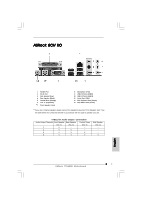
x 22.9 cm Processore: Socket 775-Pin in grado di supportare processori Intel Pentium 4 / Celeron (nella confezione 775-land LGA) Chipset: North ASRock 8CH I/O: 1 port souris PS/2, 1 port clavier PS/2 1 port série:COM 1 Italiano 1 port parallèle: Support ECP/EPP 66 ASRock 775i65PE Motherboard - ASRock 775i65PE | Quick Installation Guide - Page 67
8. Pour l'entrée microphone, cette carte mère supporte les deux modes stéréo et mono. Pour la sortie audio, cette carte mère supporte les modes 2- canaux, 4-canaux, 6-canaux et 8-canaux. Veuillez vous référer au tableau en page 3 pour effectuer la bonne connexion. 67 ASRock 775i65PE Motherboard - ASRock 775i65PE | Quick Installation Guide - Page 68
forzare l'inserimento della CPU nel socket se ci sono pin piegati. In caso contrario la CPU potrebbe essere seriamente danneggiata. Fase 1. Aprire la presa: Fase 1-1. Sbloccare la leva premendola verso il basso ed allontanandola dal gancio per liberare la linguetta. 68 ASRock 775i65PE Motherboard - ASRock 775i65PE | Quick Installation Guide - Page 69
della CPU con le due tacche nel socket. Fase 2-3. Collocare con delicatezza la CPU sulla presa con un movimento puramente verticale. Fase 2-4. Verificare che la CPU sia all'interno della presa e combaci in modo appropriato con le chiavi d'orientamento. Italiano 69 ASRock 775i65PE Motherboard - ASRock 775i65PE | Quick Installation Guide - Page 70
di carico con la linguetta della piastra di carico che si trova sulla parte inferiore della linguetta di ritenzione della leva di carico. Italiano 70 ASRock 775i65PE Motherboard - ASRock 775i65PE | Quick Installation Guide - Page 71
alimentazione della ventola al connettore ventola della CPU sulla scheda madre. Fase 6. fissare il cavo in eccesso con fascette per assicurare che il cavo non interferisca con il funzionamento della ventola o che venga a contatto con gli altri componenti. Italiano 71 ASRock 775i65PE Motherboard - ASRock 775i65PE | Quick Installation Guide - Page 72
2.3 Installazione dei moduli di memoria (DIMM) La scheda madre 775i65PE fornisce quattro alloggiamenti DIMM DDR (Double Data Rate) a 184 pin, e supporta la tecnologia Dual memoria su DDR1 e DD2, è impossibile attivare la tecnologia Dual Channel Memory. Italiano 72 ASRock 775i65PE Motherboard - ASRock 775i65PE | Quick Installation Guide - Page 73
DIMM nello slot fino a far scattare completamente in posizione i fermagli di ritegno alle due estremità e fino ad installare correttamente la DIMM nella sua sede. 73 ASRock 775i65PE Motherboard - ASRock 775i65PE | Quick Installation Guide - Page 74
della scheda con lo slot e premere con decisione finché la scheda è completamente inserita nello slot. Step 4. Agganciare la scheda allo chassis con le viti. 74 ASRock 775i65PE Motherboard Italiano - ASRock 775i65PE | Quick Installation Guide - Page 75
i jumper JL1 e JR1 sono chiusi, funzionano sia i connettori audio frontali che posteriori. Resettare la CMOS (CLRCMOS0, jumper a 2 BIOS, prima di eseguire tale operazione di cancellazione è necessario riavviare innanzitutto il sistema, e quindi spegnerlo. Italiano 75 ASRock 775i65PE Motherboard - ASRock 775i65PE | Quick Installation Guide - Page 76
di immagazzinamento interni. ATA (SATA) supportano cavi SATA per dispositivi di memoria interni. L'interfaccia SATA attuale permette velocità di trasferimento dati fino a 1.5 Gb/s. Italiano 76 ASRock 775i65PE Motherboard - ASRock 775i65PE | Quick Installation Guide - Page 77
moduli ad infrarossi optional per la trasmissione e la ricezione senza fili. Italiano Connettori audio interni Permettono di ricevere input (4-pin CD1) stereo audio da fonti di (CD1: vedi p.2 Nr. 22) suono come CD-ROM, DVD - CD1 ROM,TV tuner, o schede MPEG. 77 ASRock 775i65PE Motherboard - ASRock 775i65PE | Quick Installation Guide - Page 78
il cavo della ventolina CPU a questo connettore e far combaciare il filo nero al pin terra. Collegare la sorgente d'alimentazione ATX a questo connettore. Collegare un cavo porta giochi a questo collettore se la staffa per la porta giochi è installata. Italiano 78 ASRock 775i65PE Motherboard - ASRock 775i65PE | Quick Installation Guide - Page 79
operativo sul disco rigido SATA, è necessario controllare nella configurazione del BIOS che la configurazione della modalità operativa dell'IDE su scheda sia corretta alle istruzioni di pagina 28 del "Manuale dell'utente" contenuto nel CD di supporto. Italiano 79 ASRock 775i65PE Motherboard - ASRock 775i65PE | Quick Installation Guide - Page 80
alla CPU e alla scheda madre derivanti da trattamenti errati. Per vedere questo Demo è necessario eseguire Microsoft Media Player per poter riprodurre il file. Il demo si trova nel CD di supporto della scheda madre, al seguente indirizzo: ..\ MPEGAV \ LGA775INST.DAT 80 ASRock 775i65PE Motherboard - ASRock 775i65PE | Quick Installation Guide - Page 81
de la CPU LGA 775) Una cinta de datos IDE de conducción 80 Ultra ATA 66/100 Una cinta de datos para una unidad de disco de 3,5" Un Cable de Datos Serial ATA (SATA) Un cable serie ATA (SATA) de alimentación de disco duro (Opcional) Una protección ASRock 8CH I/O 81 ASRock 775i65PE Motherboard Español - ASRock 775i65PE | Quick Installation Guide - Page 82
: Socket de 775 agujas compatible con procesador Intel Pentium 4 / Celeron (en paquete LGA para 775 agujas ASRock 8CH I/O: 1 puerto de ratón PS/2, 1 puerto de teclado PS/2 1 Puerto serial: COM 1 1 Puerto paralelo: soporta ECP/EPP 4 puertos USB 2.0 predeterminados 82 ASRock 775i65PE Motherboard - ASRock 775i65PE | Quick Installation Guide - Page 83
bien bajo Microsoft® Windows® XP SP1/2000 SP4. Es posible que no funcione propiamente bajo Microsoft® Windows® 98/ME. 8. Para la entrada de micrófono, esta placa madre ofrece soporte para modos estéreo y mono. Para salida de audio, este placa madre ofrece 83 ASRock 775i65PE Motherboard Español - ASRock 775i65PE | Quick Installation Guide - Page 84
775 agujas en el socket, compruebe que la superficie de la CPU se encuentra limpia y no hay ninguna aguja torcida en el socket. No introduzca la CPU en el socket por la fuerza si se produce la situación anterior. Si lo hace, puede producir 84 daños graves en la CPU. ASRock 775i65PE Motherboard - ASRock 775i65PE | Quick Installation Guide - Page 85
la CPU coinciden con las teclas de alineación del socket. Step 2-3. Coloque con cuidado la CPU en el socket con un movimiento totalmente vertical. Step 2-4. Compruebe que la CPU se encuentra en el socket y la orientación coincide con la indicada por las muescas. 85 ASRock 775i65PE Motherboard Espa - ASRock 775i65PE | Quick Installation Guide - Page 86
de la CPU. A continuación se ofrece un ejemplo para ilustrar la instalación del disipador para la CPU de 775 agujas. Paso 1. Aplique el material termal de interfaz en el centro del IHS de la superficie del socket. (Aplique el material termal de interfaz) Español 86 ASRock 775i65PE Motherboard - ASRock 775i65PE | Quick Installation Guide - Page 87
el cabezal del ventilador con el conector del ventilador de la CPU en la placa madre. Fije el cable que sobre con un lazo para asegurarse de que el cable no interfiere en el funcionamiento del ventilador y tampoco entra en contacto con otros componentes. Español 87 ASRock 775i65PE Motherboard - ASRock 775i65PE | Quick Installation Guide - Page 88
2.3 Instalación de Memoria La placa 775i65PE ofrece cuatro ranuras DIMM DDR de 184 pines, y soporta Tecnología de Memoria de Doble Canal. Para la configuración de de memoria en DDR1 y DDR2, no será posible activar la Tecnología de Memoria de Doble Canal. Español 88 ASRock 775i65PE Motherboard - ASRock 775i65PE | Quick Installation Guide - Page 89
de la ranura hasta que los clips de sujeción de ambos lados queden completamente introducidos en su sitio y la DIMM se haya asentado apropiadamente. 89 ASRock 775i65PE Motherboard Español - ASRock 775i65PE | Quick Installation Guide - Page 90
desea utilizar. Paso 3. Encaje el conector de la tarjeta a la slot. Empuje firmemente la tarjeta en la slot. Paso 4. Asegure la tarjeta con tornillos. 90 ASRock 775i65PE Motherboard Español - ASRock 775i65PE | Quick Installation Guide - Page 91
Si los puentes JL1 y JR1 son cortos, tanto el conector de audio del panel frontal como del panel posterior pueden funcionar. Limpiar CMOS ( BIOS, debe arrancar primero el sistema y, a continuación, apagarlo antes de realizar la acción de borrado de CMOS. Español 91 ASRock 775i65PE Motherboard - ASRock 775i65PE | Quick Installation Guide - Page 92
1.5 Gb/s. Cable de datos de serie ATA (SATA) Ambos extremos del cable pueden conectarse al disco duro SATA o la conexión de la placa base. 92 ASRock 775i65PE Motherboard Español - ASRock 775i65PE | Quick Installation Guide - Page 93
18) Este cabezal soporta un módulo infrarrojos de transmisión y recepción wireless opcional. Conector de audio interno (4-pin CD1) (CD1: vea p. 2, N. 22) CD1 Permite recepción de input audio de fuente sónica como CDROM, DVD-ROM, TV tuner, o tarjeta MPEG. Español 93 ASRock 775i65PE Motherboard - ASRock 775i65PE | Quick Installation Guide - Page 94
el cable del ventilador de la CPU a este conector y haga coincidir el cable negro con el conector de tierra. Conecte la fuente de alimentación ATX a su cabezal. Conecte un cable de Puerto de juegos a este conector si el Puerto de Juegos está instalado. Español 94 ASRock 775i65PE Motherboard - ASRock 775i65PE | Quick Installation Guide - Page 95
ón de la opción "OnBoard IDE Operate Mode" en la BIOS está correcta según la condición de su sistema. Para obtener detalles sobre la configuración, consulte las instrucciones que aparecen en la página 28 del "Manual del usuario" en el CD de soporte. Español 95 ASRock 775i65PE Motherboard - ASRock 775i65PE | Quick Installation Guide - Page 96
ón de la BIOS, consulte el Manual del usuario (archivo PDF), que se encuentra en el CD de soporte. 4.Información de Software Support CD Esta placa-base soporta diversos tipos de sistema operativo Windows: 98SE / ME / 2000 / XP El CD de instalación que acompaña la placa-base trae todos los drivers
-
 1
1 -
 2
2 -
 3
3 -
 4
4 -
 5
5 -
 6
6 -
 7
7 -
8
-
9
-
10
-
11
-
12
-
13
-
14
-
15
-
16
-
17
-
18
-
19
-
20
-
21
-
22
-
23
-
24
-
25
-
26
-
27
-
28
-
29
-
30
-
31
-
32
-
33
-
34
-
35
-
36
-
37
-
38
-
39
-
40
-
41
-
42
-
43
-
44
-
45
-
46
-
47
-
48
-
49
-
50
-
51
-
52
-
53
-
54
-
55
-
56
-
57
-
58
-
59
-
60
-
61
-
62
-
63
-
64
-
65
-
66
-
67
-
68
-
69
-
70
-
71
-
72
-
73
-
74
-
75
-
76
-
77
-
78
-
79
-
80
-
81
-
82
-
83
-
84
-
85
-
86
-
87
-
88
-
89
-
90
-
91
-
92
-
93
-
94
-
95
-
96
 |
 |
1
ASRock
775i65PE
Motherboard
English
English
English
English
English
Copyright Notice:
Copyright Notice:
Copyright Notice:
Copyright Notice:
Copyright Notice:
No part of this installation guide may be reproduced, transcribed, transmitted, or
translated in any language, in any form or by any means, except duplication of
documentation by the purchaser for backup purpose, without written consent of
ASRock Inc.
Products and corporate names appearing in this guide may or may not be registered
trademarks or copyrights of their respective companies, and are used only for
identification or explanation and to the owners’ benefit, without intent to infringe.
Disclaimer:
Disclaimer:
Disclaimer:
Disclaimer:
Disclaimer:
Specifications and information contained in this guide are furnished for informational
use only and subject to change without notice, and should not be constructed as a
commitment by ASRock. ASRock assumes no responsibility for any errors or
omissions that may appear in this guide.
With respect to the contents of this guide, ASRock does not provide warranty of any
kind, either expressed or implied, including but not limited to the implied warranties or
conditions of merchantability or fitness for a particular purpose.
In no event shall ASRock, its directors, officers, employees, or agents be liable for
any indirect, special, incidental, or consequential damages (including damages for
loss of profits, loss of business, loss of data, interruption of business and the like),
even if ASRock has been advised of the possibility of such damages arising from any
defect or error in the guide or product.
This device complies with Part 15 of the FCC Rules. Operation is subject to the
following two conditions:
(1)
this device may not cause harmful interference, and
(2)
this device must accept any interference received, including interference that
may cause undesired operation.
ASRock Website: http://www.asrock.com
Published October 2004
Copyright
©
2004 ASRock INC. All rights reserved.