ASRock 775i65PE Quick Installation Guide - Page 16
CPU Fan Connector
 |
View all ASRock 775i65PE manuals
Add to My Manuals
Save this manual to your list of manuals |
Page 16 highlights
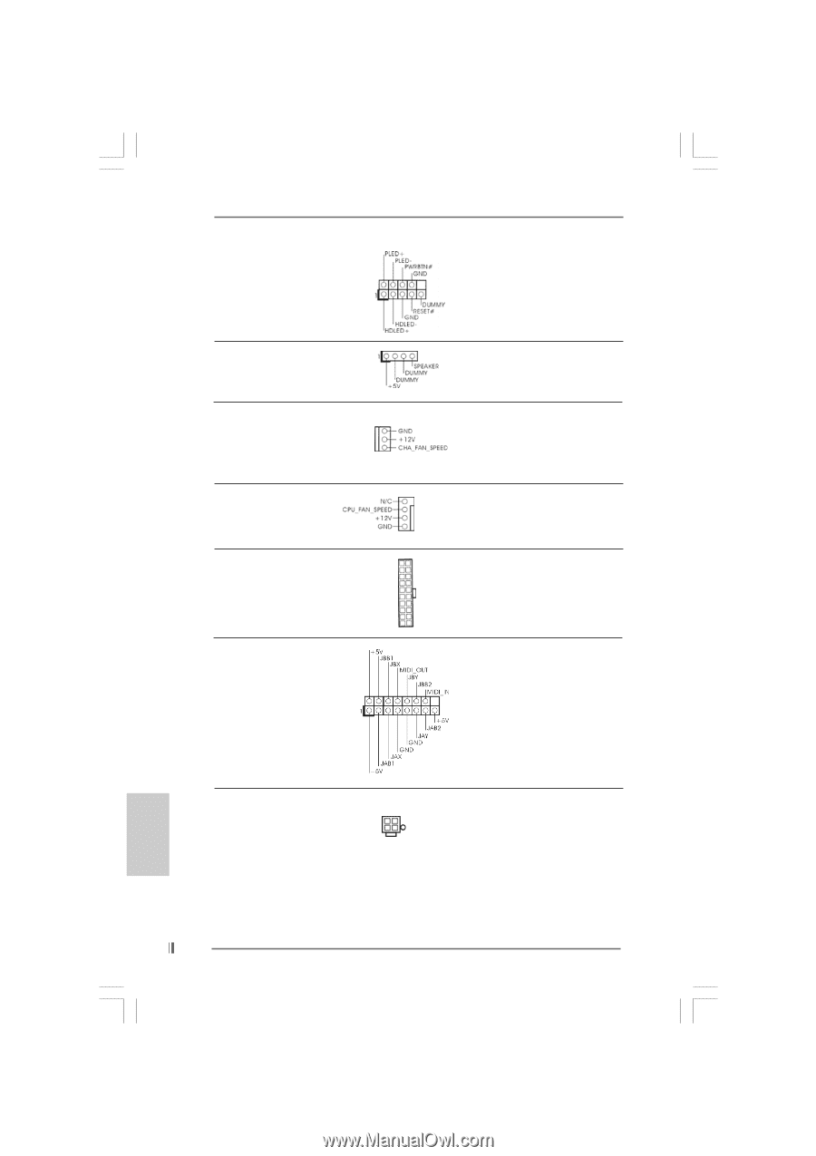
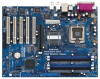
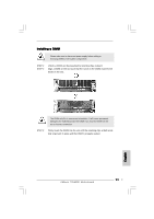
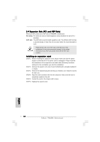
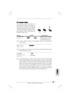
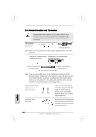
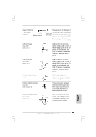
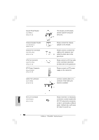
System Panel Header (9-pin PANEL1) (see p.2 No. 15) Chassis Speaker Header (4-pin SPEAKER 1) (see p.2 No. 16) Chassis Fan Connector (3-pin CHA_FAN1) (see p.2 No. 14) CPU Fan Connector (4-pin CPU_FAN1) (see p.2 No. 29) ATX Power Connector (20-pin ATXPWR1) (see p.2 No. 28) Game Port Connector (15-pin GAME1) (see p.2 No. 21) This header accommodates several system front panel functions. Please connect the chassis speaker to this header. Please connect a chassis fan cable to this connector and match the black wire to the ground pin. Please connect a CPU fan cable to this connector and match the black wire to the ground pin. Please connect an ATX power supply to this connector. Connect a Game cable to this connector if the Game port bracket is installed. English ATX 12V Connector (4-pin ATX12V1) (see p.2, No. 2) Please note that it is necessary to connect a power supply with ATX 12V plug to this connector so that it can provides sufficient power. Failing to do so will cause the failure to power up. 16 ASRock 775i65PE Motherboard
-
 1
1 -
2
-
3
-
4
-
5
-
6
-
7
-
8
-
9
-
10
-
 11
11 -
 12
12 -
 13
13 -
 14
14 -
 15
15 -
 16
16 -
 17
17 -
 18
18 -
 19
19 -
 20
20 -
 21
21 -
22
-
23
-
24
-
25
-
26
-
27
-
28
-
29
-
30
-
31
-
32
-
33
-
34
-
35
-
36
-
37
-
38
-
39
-
40
-
41
-
42
-
43
-
44
-
45
-
46
-
47
-
48
-
49
-
50
-
51
-
52
-
53
-
54
-
55
-
56
-
57
-
58
-
59
-
60
-
61
-
62
-
63
-
64
-
65
-
66
-
67
-
68
-
69
-
70
-
71
-
72
-
73
-
74
-
75
-
76
-
77
-
78
-
79
-
80
-
81
-
82
-
83
-
84
-
85
-
86
-
87
-
88
-
89
-
90
-
91
-
92
-
93
-
94
-
95
-
96
 |
 |