ASRock 845GV-M User Manual - Page 17
CD-ROM, DVD/ROM, TV - cpu support
 |
View all ASRock 845GV-M manuals
Add to My Manuals
Save this manual to your list of manuals |
Page 17 highlights
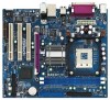
Internal Audio Connectors (4-pin CD1, 4-pin AUX1) (CD1: see p.9, No. 26) (AUX1: see p.9, No. 27) Front Panel Audio Header (9-pin AUDIO1) (see p.9, No. 25) System Panel Header (9-pin PANEL1) (see p.9, No. 15) Chassis Speaker Header (4-pin SPEAKER 1) (see p.9, No. 16) Chassis Fan Connector (3-pin CHA_FAN1) (see p.9, No. 13) CPU Fan Connector (3-pin CPU_FAN1) (see p.9, No. 5) ATX Power Header (20-pin ATXPWR1) (see p.9, No. 2) CD-R These connectors allow you GND GND CD1 to receive stereo audio input CD-L from sound sources such as AUX-R GND GND AUX1 a CD-ROM, DVD/ROM, TV AUX-L tuner card, or MPEG card. GND +5VA BACKOUT-R BACKOUT-L 1 A U D - O U T- L DUMMY A U D - O U T- R MIC-POWER MIC PLED+ PLEDPWRBTN# GND 1 DUMMY RESET# GND HDLEDHDLED+ 1 SPEAKER DUMMY DUMMY +5V This is an interface for front panel audio cable that allows convenient connection and control of audio devices. This header accommodates several system front panel functions. Please connect the chassis speaker to this header. GND +12V CHA_FAN_SPEED Please connect the chassis fan cable to this connector and match the black wire to the ground pin. GND +12V CPU_FAN_SPEED Please connect the CPU fan cable to this connector and match the black wire to the ground pin. Please connect the ATX power supply to this header. COM Port Header (9-pin COM2) (see p.9, No. 19) RRXD1 DDTR#1 DDSR#1 CCTS#1 1 RRI#1 RRTS#1 GND TTXD1 DDCD#1 This COM port header is used to support a COM port module. 17
-
 1
1 -
2
-
3
-
4
-
5
-
6
-
7
-
8
-
9
-
10
-
11
-
 12
12 -
 13
13 -
 14
14 -
 15
15 -
 16
16 -
 17
17 -
 18
18 -
 19
19 -
 20
20 -
 21
21 -
 22
22 -
23
-
24
-
25
-
26
-
27
-
28
-
29
-
30
 |
 |
