ASRock 890GX Extreme4 User Manual
ASRock 890GX Extreme4 Manual
 |
View all ASRock 890GX Extreme4 manuals
Add to My Manuals
Save this manual to your list of manuals |
ASRock 890GX Extreme4 manual content summary:
- ASRock 890GX Extreme4 | User Manual - Page 1
890GX Extreme4 User Manual Version 1.0 Published July 2010 Copyright©2010 ASRock INC. All rights reserved. 1 - ASRock 890GX Extreme4 | User Manual - Page 2
commitment by ASRock. ASRock assumes no responsibility for any errors or omissions that may appear in this manual. With respect to the contents of this manual, ASRock does not , USA ONLY The Lithium battery adopted on this motherboard contains Perchlorate, a toxic substance controlled in Perchlorate - ASRock 890GX Extreme4 | User Manual - Page 3
and Connectors 32 2.10 Smart Switches 37 2.11 Dr. Debug 38 2.12 Serial ATA3 (SATA3) Hard Disks Installation 41 2.13 Hot Plug and Hot Swap Functions for SATA3 HDDs 41 2.14 SATA3 HDD Hot Plug Feature and Operation Guide 42 2.15 Driver Installation Guide 44 2.16 Installing Windows® 7 / 7 64-bit - ASRock 890GX Extreme4 | User Manual - Page 4
BIOS Menu Bar 48 3.1.2 Navigation Keys 49 3.2 Main Screen 49 3.3 OC Tweaker Screen 50 3.4 Advanced Screen 58 3.4.1 CPU Screen 71 4 . Software Support 72 4.1 Install Operating System 72 4.2 Support CD Information 72 4.2.1 Running Support CD 72 4.2.2 Drivers Menu 72 4.2.3 Utilities Menu - ASRock 890GX Extreme4 | User Manual - Page 5
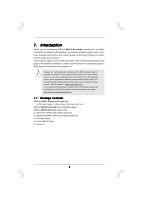
about the model you are using. www.asrock.com/support/index.asp 1.1 Package Contents ASRock 890GX Extreme4 Motherboard (ATX Form Factor: 12.0-in x 9.6-in, 30.5 cm x 24.4 cm) ASRock 890GX Extreme4 Quick Installation Guide ASRock 890GX Extreme4 Support CD 4 x Serial ATA (SATA) Data Cables (Optional - ASRock 890GX Extreme4 | User Manual - Page 6
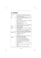
1.2 Specifications Platform CPU Chipset Memory Expansion Slot Graphics - ATX Form Factor: 12.0-in x 9.6-in, 30.5 cm x 24.4 cm - All Solid Capacitor design (100% Japan-made high-quality Conductive Polymer Capacitors) - Support for Socket AM3 processors: AMD PhenomTM II X6 / X4 / X3 / X2 (except 920 - ASRock 890GX Extreme4 | User Manual - Page 7
USB 3.0 ports) by NEC UPD720200, supports USB 1.0/2.0/3.0 up to 5Gb/s - 5 x SATA3 6.0Gb/s connectors - 1 x IR header - 1 x COM port header - 1 x IEEE 1394 header - 1 x HDMI_SPDIF header - 1 x Power LED header - CPU/Chassis/Power FAN connector - 24 pin ATX power connector - 8 pin 12V power connector - ASRock 890GX Extreme4 | User Manual - Page 8
BIOS - Supports "Plug and Play" - ACPI 1.1 Compliance Wake Up Events - Supports jumperfree - SMBIOS 2.3.1 Support - CPU, VCCM, NB, SB Voltage Multi-adjustment Support CD - Drivers, Utilities, AntiVirus Software (Trial Version), AMD OverDriveTM Utility, AMD Live! Explorer, AMD Fusion, ASRock - ASRock 890GX Extreme4 | User Manual - Page 9
the upgrade CPU performance with a better price. Please be noted that UCC feature is supported with AM3 CPU only, and in addition, not every AM3 CPU can support this function because some CPU's hidden core may be malfunctioned. 2. This motherboard supports Untied Overclocking Technology. Please - ASRock 890GX Extreme4 | User Manual - Page 10
ASRock website: http://www.asrock.com 10. ASRock Instant Flash is a BIOS flash utility embedded in Flash ROM. This convenient BIOS update tool allows you to update system BIOS install the ASRock AIWI utility either from ASRock official website or ASRock software support CD to your motherboard, and - ASRock 890GX Extreme4 | User Manual - Page 11
mode (S4) or power off (S5). With APP Charger driver installed, you can easily enjoy the marvelous charging experience than ever. ASRock website: http://www.asrock.com/Feature/AppCharger/index.asp 14. Although this motherboard offers stepless control, it is not recommended to perform over-clocking - ASRock 890GX Extreme4 | User Manual - Page 12
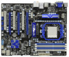
CODEC PCIE2 Sideport memory 128MB PCI Express 2.0 PCI1 Support 6-Core CPU NEC USB 3.0 PCIE3 890GX Extreme4 PCI2 CMOS BATTERY ErP/EuP Ready SATA3 6Gb/s AMD SB850 Chipset PCIE4 Designed in Taipei PCI3 Front USB 3.0 8Mb BIOS CLRCMOS1 1 Dr. Debug SATA3 (PORT 2) SATA4 (PORT 3) SATA5 (PORT - ASRock 890GX Extreme4 | User Manual - Page 13
1 . 4 I/O Panel 12 34 58 69 7 10 17 16 1 USB 2.0 Ports (USB45) 2 VGA/D-Sub Port 3 USB 2.0 Ports (USB23) * 4 LAN RJ-45 Port 5 Central / Bass (Orange) 6 Rear Speaker (Black) 7 Optical SPDIF Out Port 8 Line In (Light Blue) ** 9 Front Speaker (Lime) 15 14 13 12 11 10 11 12 *** 13 14 15 16 17 - ASRock 890GX Extreme4 | User Manual - Page 14
Primary output" to use Rear Speaker, Central/Bass, and Front Speaker, or select "Realtek HDA Audio 2nd output" to use front panel audio. *** eSATA3 connector supports SATA Gen3 in cable 1M. 14 - ASRock 890GX Extreme4 | User Manual - Page 15
, peripherals, and/or components. 1. Unplug the power cord from the wall socket before touching any component. 2. To avoid damaging the motherboard components due to static electricity, NEVER place your motherboard directly on the carpet or the like. Also remember to use a grounded wrist strap - ASRock 890GX Extreme4 | User Manual - Page 16
Socker Corner Small Triangle STEP 2 / STEP 3: Match The CPU Golden Triangle To The Socket Corner Small Triangle STEP 4: Push Down And Lock The Socket Lever 2.2 Installation of CPU Fan and Heatsink After you install the CPU into this motherboard, it is necessary to install a larger heatsink and - ASRock 890GX Extreme4 | User Manual - Page 17
2.3 Installation of Memory Modules (DIMM) This motherboard provides four 240-pin DDR3 (Double Data Rate 3) DIMM slots, and supports Dual Channel Memory Technology. For dual channel configuration, you always need to install identical (the same brand, speed, size and chiptype) DDR3 DIMM pair in - ASRock 890GX Extreme4 | User Manual - Page 18
matches the break on the slot. notch break notch break The DIMM only fits in one correct orientation. It will cause permanent damage to the motherboard and the DIMM if you force the DIMM into the slot at incorrect orientation. Step 3. Firmly insert the DIMM into the slot until the retaining - ASRock 890GX Extreme4 | User Manual - Page 19
lane width graphics cards, or used to install PCI Express graphics cards to support CrossFireXTM function. PCIE4 (PCIE x16 slot; Blue) is used for PCI the installation. Step 2. Remove the system unit cover (if your motherboard is already installed in a chassis). Step 3. Remove the bracket facing - ASRock 890GX Extreme4 | User Manual - Page 20
after your system boots. If you haven't installed onboard VGA driver yet, please install onboard VGA driver from our support CD to your system and restart your computer. Then you can start to use dual monitor function on this motherboard. 1. DVI-D and HDMI ports cannot function at the same time - ASRock 890GX Extreme4 | User Manual - Page 21
memory. If you do not adjust the BIOS setup, the default value of "Share Memory", [Auto], will disable VGA/D-Sub function when the add-on VGA card is inserted to this motherboard. 4. Install the onboard VGA driver and the add-on PCI Express VGA card driver to your system. If you have installed - ASRock 890GX Extreme4 | User Manual - Page 22
function is supported on this motherboard. To use HDCP function with this motherboard, you need to adopt the monitor that supports HDCP function as well. Therefore, you can enjoy the superior display quality with high-definition HDCP encryption contents. Please refer to below instruction for more - ASRock 890GX Extreme4 | User Manual - Page 23
Guide This motherboard supports supported with Windows® XP with Service Pack 2 / VistaTM / 7 OS. 3-way CrossFireXTM and Quad CrossFireXTM feature are supported with Windows® VistaTM / 7 OS only. Please check AMD website for ATITM CrossFireXTM driver updates manuals for detailed installation guide. - ASRock 890GX Extreme4 | User Manual - Page 24
Bridge Interconnects on the top of Radeon graphics cards. (CrossFire Bridge is provided with the graphics card you purchase, not bundled with this motherboard. Please refer to your graphics card vendor for details.) CrossFire Bridge or Step 3. Connect the DVI monitor cable to the DVI connector - ASRock 890GX Extreme4 | User Manual - Page 25
Bridge to connect Radeon graphics cards on PCIE3 and PCIE4 slots. (CrossFireTM Bridge is provided with the graphics card you purchase, not bundled with this motherboard. Please refer to your graphics card vendor for details.) 25 - ASRock 890GX Extreme4 | User Manual - Page 26
CrossFireTM Bridge Step 5. Connect the DVI monitor cable to the DVI connector on the Radeon graphics card on PCIE2 slot. (You may use the DVI to D-Sub adapter to convert the DVI connector to D-Sub interface, and then connect the D-Sub monitor cable to the DVI to D-Sub adapter.) 26 - ASRock 890GX Extreme4 | User Manual - Page 27
utility to uninstall any previously installed Catalyst drivers prior to installation. Please check AMD website for ATITM driver updates. Step 3. Step 4. Step 5. Install the required drivers to your system. For Windows® XP OS: A. ATITM recommends Windows® XP Service Pack 2 or higher to be installed - ASRock 890GX Extreme4 | User Manual - Page 28
is used only for identification or explanation and to the owners' benefit, without intent to infringe. * For further information of ATITM CrossFireXTM technology, please check AMD website for updates and details. 28 - ASRock 890GX Extreme4 | User Manual - Page 29
or 5450 series graphics processor and a motherboard based on an AMD 890GX integrated chipset, all operating in a Windows® VistaTM / 7 environment. Please refer to below PCI Express graphics card support list for ATITM Hybrid CrossFireXTM. For the future update of more compatible PCI Express graphics - ASRock 890GX Extreme4 | User Manual - Page 30
used only for identification or explanation and to the owners' benefit, without intent to infringe. * For further information of ATITM Hybrid CrossFireXTM technology, please check AMD website for up dates and details. 30 - ASRock 890GX Extreme4 | User Manual - Page 31
short pin2 and pin3 on CLRCMOS1 for 5 seconds. However, please do not clear the CMOS right after you update the BIOS. If you need to clear the CMOS when you just finish updating the BIOS, you must boot up the system first, and then shut it down before you do the clear-CMOS action - ASRock 890GX Extreme4 | User Manual - Page 32
SATA data cable can be connected to the SATA3 hard disk or the SATA3 connector on this motherboard. Please connect the black end of SATA power cable to the power connector on each drive I/O panel, there are three USB 2.0 headers on this motherboard. Each USB 2.0 header can support two USB 2.0 ports. - ASRock 890GX Extreme4 | User Manual - Page 33
panel, there is one USB 3.0 header on this motherboard. This USB 3.0 header can support two USB 3.0 ports. Infrared Module Header (5-pin IR1 supports Jack Sensing, but the panel wire on the chassis must support HDA to function correctly. Please follow the instruction in our manual and chassis manual - ASRock 890GX Extreme4 | User Manual - Page 34
Connect the power switch, reset switch and system status indicator on the chassis to this header according to the pin assignments below. Note the positive and negative pins before connecting the cables. PWRBTN (Power Switch): Connect to the power switch on the chassis front panel. You may configure - ASRock 890GX Extreme4 | User Manual - Page 35
through BIOS or OC Tuner utility. (3-pin PWR_FAN1) (see p.12 No. 43) CPU Fan Connectors (4-pin CPU_FAN1) (see p.12 No. 4) 1 2 3 4 Please connect the CPU fan cable to this connector and match the black wire to the ground pin. Though this motherboard provides 4-Pin CPU fan (Quiet Fan) support - ASRock 890GX Extreme4 | User Manual - Page 36
No. 22) Serial port Header (9-pin COM1) (see p.12 No.32) 4-Pin ATX 12V Power Supply Installation 4 1 RXTPAM_0 GND RXTPBM_0 +12V GND 1 +12V RXTPBP_0 GND header (FRONT_1394) on this motherboard. This IEEE 1394 header can support one IEEE 1394 port. This COM1 header supports a serial port module. - ASRock 890GX Extreme4 | User Manual - Page 37
2.10 Smart Switches This motherboard has three smart switches: power switch, reset switch and clear CMOS switch, allowing users to quickly turn on/off or reset the system or clear - ASRock 890GX Extreme4 | User Manual - Page 38
Dr. Debug Dr. Debug is used to provide code information, which makes troubleshooting even easier. Please see the diagrams below for reading the Dr. Debug codes. The Bootblock initialization code pointer for future use in PMM. Copying Main BIOS into memory. Leaves all RAM below 1MB Read-Write - ASRock 890GX Extreme4 | User Manual - Page 39
BIOS modules on POST entry and GPNV area. Initialized CMOS as mentioned in the Kernel Variable "wCMOSFlags." Check CMOS diagnostic byte to determine if battery power is OK and CMOS checksum is OK. Verify CMOS checksum manually by reading storage area. If the CMOS checksum is bad, update Early CPU - ASRock 890GX Extreme4 | User Manual - Page 40
Parallel ports, serial ports, and coprocessor in CPU, etc.) successfully installed in the system and update the BDA, EBDA, etc. 50 Programming error. 87 Execute BIOS setup if needed / requested. 8C Late POST initialization of chipset registers. 8D Build ACPI tables (if ACPI is supported) - ASRock 890GX Extreme4 | User Manual - Page 41
Serial ATA3 (SATA3) Hard Disks Installation This motherboard adopts AMD SB850 chipset that supports Serial ATA3 (SATA3) hard disks and RAID functions. You may install SATA3 hard disks on this motherboard for internal storage devices. This section will guide you to install the SATA3 hard disks. STEP - ASRock 890GX Extreme4 | User Manual - Page 42
is installed into system properly. The latest SATA3 driver is available on our support website: www.asrock.com 4. Make sure to use the SATA power cable & data cable, which are from our motherboard package. 5. Please follow below instructions step by step to reduce the risk of HDD crash or data - ASRock 890GX Extreme4 | User Manual - Page 43
cable to (White) to the power supply 1x4-pin cable. the motherboard's SATA3 connector. SATA power cable 1x4-pin power connector (White) Step attention, before you process the Hot Unplug: Please do follow below instruction sequence to process the Hot Unplug, improper procedure will cause the SATA3 - ASRock 890GX Extreme4 | User Manual - Page 44
below steps. STEP 1: Set up BIOS. A. Enter BIOS SETUP UTILITY Advanced screen Storage Configuration. B. Set the "SATA Operation Mode" option to [RAID]. STEP 2: Make a SATA3 Driver Diskette. (Please use USB floppy or floppy disk.) A. Insert the ASRock Support CD into your optical drive to - ASRock 890GX Extreme4 | User Manual - Page 45
the RAID installation guide in the Support CD for proper configuration. Please refer to the BIOS RAID installation guide part of the document in the following path in the Support CD: .. \ RAID Installation Guide STEP 3: Make a SATA3 Driver Diskette. Make a SATA3 driver diskette by following - ASRock 890GX Extreme4 | User Manual - Page 46
the SATA3 driver diskette containing the AMD AHCI driver. After reading the floppy disk, the driver will be presented. Select the driver to install according to the OS you install. Using SATA3 HDDs without NCQ and Hot Plug functions (IDE mode) STEP 1: Set up BIOS. A. Enter BIOS SETUP UTILITY - ASRock 890GX Extreme4 | User Manual - Page 47
Technology This motherboard supports Untied Overclocking Technology, which means during overclocking, FSB enjoys better margin due to fixed PCI / PCIE buses. Before you enable Untied Overclocking function, please enter "Overclock Mode" option of BIOS setup to set the selection from [Auto] to [Manual - ASRock 890GX Extreme4 | User Manual - Page 48
BIOS SETUP UTILITY to configure your system. The SPI Memory on the motherboard stores the BIOS SETUP UTILITY. You may run the BIOS Because the BIOS software is constantly being updated, the following BIOS setup screens set up overclocking features Advanced To set up the advanced BIOS features H/W - ASRock 890GX Extreme4 | User Manual - Page 49
Exit System Overview System Time System Date [17:00:09] [Thu 07/15/2010] BIOS Version : 890GX Extreme4 P1.00 Processor Type : AMD Phenom(tm) II X2 555 Processor (64bit) Processor Speed : 3200MHz Microcode Update : 100F43/10000B6 L1 Cache Size : 256KB L2 Cache Size : 2048KB L3 Cache Size : 6144KB - ASRock 890GX Extreme4 | User Manual - Page 50
to your mGPU and motherboard. It should be done at your own risk and expense. CPU Configuration Overclock Mode Use this to select Overclock Mode. The default value is [Auto]. Configuration options: [Auto] and [Manual]. CPU Frequency (MHz) Use this option to adjust CPU frequency. PCIE Frequency (MHz - ASRock 890GX Extreme4 | User Manual - Page 51
, which means you can enjoy the upgrade CPU performance with a better price. Please be noted that UCC feature is supported with AM3 CPU only, and in addition, not every AM3 CPU can support this function because some CPU's hidden core may be malfunctioned. CPU Active Core Control This allows you to - ASRock 890GX Extreme4 | User Manual - Page 52
not recommended to adjust the value of this item. CPU Voltage It allows you to adjust the value of CPU voltage. However, for safety and system stability, and [16 Bit]. Memory Configuration Memory Clock This item can be set by the code using [Auto]. You can set one of the standard values as listed: [ - ASRock 890GX Extreme4 | User Manual - Page 53
Memory Timing BIOS SETUP UTILITY OC Tweaker Memory Timing Memory Controller Mode Power Down Enable Bank Interleaving Channel Interleaving CAS Latency (CL) 9 TRCD 12 TRP 12 TRAS 30 - ASRock 890GX Extreme4 | User Manual - Page 54
TRRD Use this to adjust TRRD values. Configuration options: [Auto], [4CLK] to [7CLK]. The default value is [Auto]. TWTR Use this to adjust TWTR values. Configuration options: [Auto], [4CLK] to [7CLK]. The default value is [Auto]. TWR Use this to adjust TWR values. Configuration options: [Auto], [ - ASRock 890GX Extreme4 | User Manual - Page 55
CHA ADDR/CMD Setup Use this to adjust values for CHA ADDR/CMD Setup feature. Configuration options: [Auto], [1/2CLK] and [1CLK]. The default value is [Auto]. CHA CS/ODT Delay Use this to adjust values for CHA CS/ODT Delay feature. Configuration options: [Auto], [No Delay], [1/64CLK] to [31/64CLK]. - ASRock 890GX Extreme4 | User Manual - Page 56
CHA Processor ODT Use this to adjust values for CHA Processor ODT. Configuration options: [Auto], [240 ohms], [120 ohms] and [60 ohms]. The default value is [Auto]. CHB CKE Drive Use this to adjust values for CHB CKE Drive. Configuration options: [Auto], [1.00x], [1.25x], [1.50x] and [2.00x]. The - ASRock 890GX Extreme4 | User Manual - Page 57
SidePort Voltage Use this to select SidePort voltage. Configuration options: [Auto], [1.50V] and [1.80V]. The default value is [Auto]. CPU VDDA Voltage Use this to select CPU VDDA voltage. Configuration options: [Auto], [2.56V] and [2.70V]. The default value is [Auto]. PCIE VDDA Voltage Use this to - ASRock 890GX Extreme4 | User Manual - Page 58
wrong values in below sections may cause system to malfunction. CPU Configuration Chipset Configuration ACPI Configuration Storage Configuration PCIPnP Configuration SuperIO Configuration USB Configuration BIOS Update Utility ASRock Instant Flash Select Screen Select Item Enter Go to Sub Screen - ASRock 890GX Extreme4 | User Manual - Page 59
the additional hardware capabilities provided by AMD-V. The default value is [Enabled]. Configuration options: [Enabled] and [Disabled]. Enhance Halt State All processors support the Halt State (C1). The C1 state is supported through the native processor instructions HLT and MWAIT and requires no - ASRock 890GX Extreme4 | User Manual - Page 60
3.4.2 Chipset Configuration BIOS SETUP UTILITY Advanced Chipset Settings Onboard 80 Port LED Onboard HD Audio Front Panel [Auto] [Auto] [Auto] Onboard Lan Energy Efficient Ethernet Dr. LAN Link speed : 10Mbps [Enabled] [Disabled] Onboard IEEE 1394 [Enabled] Primary Graphics Adapter Internal - ASRock 890GX Extreme4 | User Manual - Page 61
options: [Auto], [32MB], [64MB], [128MB], [256MB] and [512MB]. Onboard HDMI HD Audio This allows you to enable or disable the onboard HDMI HD Audio in AMD 890GX. If you use Dual-link DVI monitor, please set this item to [Disabled]. Surround View This allows you to enable or disable the Surround View - ASRock 890GX Extreme4 | User Manual - Page 62
3.4.3 ACPI Configuration BIOS SETUP UTILITY Advanced ACPI Settings Suspend To RAM Check Ready Bit Away Mode Support Restore on AC / Power Loss Ring-In Power On PCI Devices Power On PS set this option to [Enabled] if you plan to use this motherboard to submit Windows® VistaTM certification. 62 - ASRock 890GX Extreme4 | User Manual - Page 63
this item to RAID mode, it is suggested to install SATA ODD driver on SATA5 port. AMD AHCI BIOS ROM Use this item to enable or disable AMD AHCI BIOS ROM. This option appears only when you set "SATA Operation Mode" to SATA6 port is used internally, not eSATA, please set [Auto] for SATA3 support. 63 - ASRock 890GX Extreme4 | User Manual - Page 64
BIOS SETUP UTILITY Advanced SATA3_1 Master Device Vendor Size LBA Mode Block Mode PIO Mode Async DMA Ultra DMA S.M.A.R.T. :Hard Disk :MAXTOR 6L080J4 :80.0 GB :Supported :16Sectors :4 :MultiWord DMA-2 :Ultra DMA-6 :Supported selecting the hard disk information into BIOS, use a disk utility, such - ASRock 890GX Extreme4 | User Manual - Page 65
], [Enabled]. 32Bit Data Transfer Use this item to enable 32-bit access to maximize the IDE hard disk data transfer rate. 3.4.5 PCIPnP Configuration BIOS SETUP UTILITY Advanced Advanced PCI / PnP Settings PCI Latency Timer PCI IDE BusMaster [32] [Enabled] Value in units of PCI clocks for PCI - ASRock 890GX Extreme4 | User Manual - Page 66
SETUP UTILITY Advanced Configure Super IO Chipset Serial Port Address Infrared Port Address PS/2 Port Type [3F8 / IRQ4] [Disabled] [Auto] Allow BIOS to Select Serial Port Base Addresses. +F1 F9 F10 ESC Select Screen Select Item Change Option General Help Load Defaults Save and Exit Exit v02 - ASRock 890GX Extreme4 | User Manual - Page 67
Use this item to enable or disable the use of USB controller. Legacy USB Support Use this option to select legacy support for USB devices. There are four configuration options: [Enabled], [Auto], [Disabled] and [BIOS Setup Only]. The default value is [Enabled]. Please refer to below descriptions for - ASRock 890GX Extreme4 | User Manual - Page 68
of the CPU temperature, motherboard temperature, CPU fan speed, chassis fan speed, and the critical voltage. BIOS SETUP UTILITY allows you to set the chassis fan 2 speed. Configuration options: [Full On] and [Manual Mode]. The default is value [Full On]. Chassis Fan 3 Setting This allows you to - ASRock 890GX Extreme4 | User Manual - Page 69
this section, it will display the available devices on your system for you to configure the boot settings and the boot priority. BIOS SETUP UTILITY Main OC Tweaker Advanced H/W Monitor Boot Security Exit Boot Settings Boot Settings Configuration Configure Settings during System Boot. 1st Boot - ASRock 890GX Extreme4 | User Manual - Page 70
this section, you may set or change the supervisor/user password for the system. For the user password, you may also clear it. BIOS SETUP UTILITY Main OC Tweaker Advanced H/W Monitor Boot Security Exit Security Settings Supervisor Password : Not Installed User Password : Not Installed Change - ASRock 890GX Extreme4 | User Manual - Page 71
Changes When you select this option, it will pop-out the following message, "Discard changes?" Select [OK] to discard all changes. Load BIOS Defaults Load BIOS default values for all the setup questions. F9 key can be used for this operation. Load Performance Setup Default This performance setup - ASRock 890GX Extreme4 | User Manual - Page 72
install the necessary drivers to activate the devices. 4.2.3 Utilities Menu The Utilities Menu shows the applications software that the motherboard supports. Click on a specific item then follow the installation wizard to install it. 4.2.4 Contact Information If you need to contact ASRock or want to
-
 1
1 -
 2
2 -
 3
3 -
 4
4 -
 5
5 -
 6
6 -
 7
7 -
8
-
9
-
10
-
11
-
12
-
13
-
14
-
15
-
16
-
17
-
18
-
19
-
20
-
21
-
22
-
23
-
24
-
25
-
26
-
27
-
28
-
29
-
30
-
31
-
32
-
33
-
34
-
35
-
36
-
37
-
38
-
39
-
40
-
41
-
42
-
43
-
44
-
45
-
46
-
47
-
48
-
49
-
50
-
51
-
52
-
53
-
54
-
55
-
56
-
57
-
58
-
59
-
60
-
61
-
62
-
63
-
64
-
65
-
66
-
67
-
68
-
69
-
70
-
71
-
72
 |
 |

1
890GX Extreme4
User Manual
Version 1.0
Published July 2010
Copyright©2010 ASRock INC. All rights reserved.