ASRock 939NF4G-SATA2 User Manual
ASRock 939NF4G-SATA2 Manual
 |
View all ASRock 939NF4G-SATA2 manuals
Add to My Manuals
Save this manual to your list of manuals |
ASRock 939NF4G-SATA2 manual content summary:
- ASRock 939NF4G-SATA2 | User Manual - Page 1
939NF4G-SATA2 User Manual Version 1.0 Published August 2005 Copyright©2005 ASRock INC. All rights reserved. 1 - ASRock 939NF4G-SATA2 | User Manual - Page 2
any form or by any means, except duplication of documentation by the purchaser for backup purpose, without written consent of ASRock Inc. Products and corporate names appearing in this manual may or may not be registered trademarks or copyrights of their respective companies, and are used only for - ASRock 939NF4G-SATA2 | User Manual - Page 3
Disk Setup Guide 21 2.9 Serial ATA (SATA) / Serial ATAII (SATAII) Hard Disks Installation 22 2.10 Installing Windows 2000 / XP / XP 64-bit Without RAID Functions 23 2.11 Installing Windows 2000 / XP / XP 64-bit With RAID Functions. 23 2.12 Untied Overclocking Technology 23 3 . BIOS SETUP UTILITY - ASRock 939NF4G-SATA2 | User Manual - Page 4
4 . Software Support 40 4.1 Install Operating System 40 4.2 Support CD Information 40 4.2.1 Running Support CD 40 4.2.2 Drivers Menu 40 4.2.3 Utilities Menu 40 4.2.4 Contact Information 40 APPENDIX: AMD's Cool 'n' QuietTM Technology ...... 41 4 - ASRock 939NF4G-SATA2 | User Manual - Page 5
latest memory and CPU support lists on ASRock website as well. ASRock website http://www.asrock.com 1.1 Package Contents 1 x ASRock 939NF4G-SATA2 Motherboard (Micro ATX Form Factor: 9.6-in x 8.8-in, 24.4 cm x 22.4 cm) 1 x ASRock 939NF4G-SATA2 Quick Installation Guide 1 x ASRock 939NF4G-SATA2 Support - ASRock 939NF4G-SATA2 | User Manual - Page 6
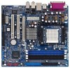
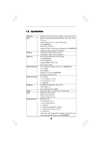
1.2 Specifications Platform CPU Chipset Memory Hybrid Booster Expansion Slot Graphics Audio LAN Rear Panel I/O - Micro ATX Form Factor: 9.6-in x 8.8-in, 24.4 cm x 22.4 cm - 939-Pin Socket Supporting AMD AthlonTM 64 / 64FX / 64X2 Processor - Supports AMD's Cool 'n' QuietTM Technology (see CAUTION - ASRock 939NF4G-SATA2 | User Manual - Page 7
panel audio connector - 2 x USB 2.0 headers (support 4 USB 2.0 ports) (see CAUTION 8) - 4Mb AMI BIOS - AMI Legal BIOS - Supports "Plug and Play" - ACPI 1.1 Compliance Wake Up Events - SMBIOS 2.3.1 Support - Drivers, Utilities, AntiVirus Software - CPU Temperature Sensing - Motherboard Temperature - ASRock 939NF4G-SATA2 | User Manual - Page 8
K8 939-pin CPU can support AMD's Cool 'n' QuietTM technology, please check AMD's website for details. 2. This motherboard supports Untied Overclocking Technology. Please read "Untied Overclocking Technology" on page 23 for details. 3. This motherboard supports Dual Channel Memory Technology. Before - ASRock 939NF4G-SATA2 | User Manual - Page 9
ATX12V1 5 22.4cm (8.8-in) 939NF4G-SATA2 FSB1GHz 6 7 DDR400 PS2 Keyboard IDE2 Dual Channel Dual core CPU PARALLEL PORT DDR1 (64/72 bit, 184-piFnSmBo8du0le0) DDR2 (64/72 bit, 184-pin module) DDR3 (64/72 bit, 184-piFnSmBo8du0le0) DDR4 (64/72 bit, 184-pin module) SOCKET 939 VGA1 1 32 31 30 - ASRock 939NF4G-SATA2 | User Manual - Page 10
1.4 ASRock 8CH I/O 1 2 3 6 4 7 5 8 13 12 11 10 1 Parallel Port 2 RJ-45 Port 3 the table below for connection details in accordance with the type of speaker you use. TABLE for Audio Output Connection Audio Output Channels Front Speaker Rear Speaker Central / Bass (No. 7) (No. 4) (No. 5) - ASRock 939NF4G-SATA2 | User Manual - Page 11
2. Installation 939NF4G-SATA2 is a Micro ATX form factor (9.6-in x 8.8-in, 24.4 cm x 22.4 cm) motherboard. Before you install the motherboard, study the configuration of your chassis to ensure that the motherboard fits into it. Pre-installation Precautions Take note of the following precautions - ASRock 939NF4G-SATA2 | User Manual - Page 12
Golden Triangle STEP 1: Lift Up The Socket Lever Socket Corner STEP 2 / STEP 3: STEP 4: Match The CPU Golden Triangle Push Down And Lock To The Socket Corner The Socket Lever 2.2 Installation of CPU Fan and Heatsink After you install the CPU into this motherboard, it is necessary to install - ASRock 939NF4G-SATA2 | User Manual - Page 13
2.3 Installation of Memory Modules (DIMM) 939NF4G-SATA2 motherboard provides four 184-pin DDR (Double Data Rate) DIMM slots, and supports Dual Channel Memory Technology. For dual channel configuration, you always need to install identical (the same brand, speed, size and chip-type) DDR DIMM pair in - ASRock 939NF4G-SATA2 | User Manual - Page 14
matches the break on the slot. notch break notch break The DIMM only fits in one correct orientation. It will cause permanent damage to the motherboard and the DIMM if you force the DIMM into the slot at incorrect orientation. Step 3. Firmly insert the DIMM into the slot until the retaining - ASRock 939NF4G-SATA2 | User Manual - Page 15
motherboard supports Multi Monitor upgrade. With the internal onboard VGA and the external add-on PCI Express VGA card, you can easily enjoy the benefits of Multi Monitor feature. If you plan to enable the function of onboard VGA, please enter the option "Share Memory" of BIOS to adjust the memory - ASRock 939NF4G-SATA2 | User Manual - Page 16
5V +5VSB +5VSB (standby) for PS/2 or USB wake up events. Note: To select +5VSB, it requires short, both the front panel and the rear panel audio connectors can work. Clear CMOS Jumper (CLRCMOS1) ( update the BIOS. If you need to clear the CMOS when you just finish updating the BIOS, you must boot - ASRock 939NF4G-SATA2 | User Manual - Page 17
support SATA II or SATA hard disk for internal storage devices. The current SATA II interface allows up to 3.0 Gb/s data transfer rate. Serial ATA (SATA) Data Cable Either end of the SATA data cable can be connected to the SATA / SATAII hard disk or the SATAII connector on the motherboard - ASRock 939NF4G-SATA2 | User Manual - Page 18
: see p.9 No. 30) IRTX +5VSB DUMMY 1 GND IRRX CD-R GND GND CD-L CD1 This header supports an optional wireless transmitting and receiving infrared module. This connector allows you to receive stereo audio input from sound sources such as a CD-ROM, DVD-ROM, TV tuner card, or MPEG card. Front Panel - ASRock 939NF4G-SATA2 | User Manual - Page 19
chassis fan cable to this connector and match the black wire to the ground pin. Please connect the CPU fan cable to this connector and match the black wire to the ground pin. Please connect an ATX power header if the Game port bracket is installed. This COM1 connector supports a serial port module. - ASRock 939NF4G-SATA2 | User Manual - Page 20
guide. Some default setting of SATAII hard disks may not be at SATAII mode, which operate with the best performance. In order to enable SATAII function, please follow the below instruction If pin 3 and pin 4 are shorted, SATA 1.5Gb/s will be enabled. On the other .com/hdd/support/download.htm The - ASRock 939NF4G-SATA2 | User Manual - Page 21
nForce 410 MCP southbridge chipset that supports Serial ATA (SATA) / Serial ATAII (SATAII) hard disks and RAID functions. You may install SATA / SATAII hard disks on this motherboard for internal storage devices. This section will guide you to install the SATA / SATAII hard disks. STEP 1: Install - ASRock 939NF4G-SATA2 | User Manual - Page 22
.htm#the_integrated_installation_fmay STEP 1: Make a SATA / SATAII Driver Diskette. A. Insert the ASRock Support CD into your optical drive to boot your system. B. During POST at the beginning of system boot-up, press key, and then a window for boot devices selection appears. Please - ASRock 939NF4G-SATA2 | User Manual - Page 23
", which is located in the folder at the following path: .. \Information\Manual\RAID Utility for Windows Guide 2.12 Untied Overclocking Technology This motherboard supports Untied Overclocing Technology, which means during overclocking, FSB enjoys better margin due to fixed PCI / PCIE buses. Before - ASRock 939NF4G-SATA2 | User Manual - Page 24
BIOS SETUP UTILITY to configure your system. The Flash Memory on the motherboard stores the BIOS SETUP UTILITY. You may run the BIOS Because the BIOS software is constantly being updated, the following BIOS setup screens and BIOS features H/W Monitor To display current hardware status Boot To - ASRock 939NF4G-SATA2 | User Manual - Page 25
System Time [17:00:09] System Date [Tue 08/09/2005] BIOS Version : 939NF4G-SATA2 BIOS P1.0 Processor Type : AMD Athlon(tm) 64 Processor 3400+ (64bit supported) Processor Speed : 2200 MHz Microcode Update : F7A/3A L1 Cache Size : 128KB L2 Cache Size : 512KB Total Memory DDR 1 DDR 2 DDR - ASRock 939NF4G-SATA2 | User Manual - Page 26
CPU Configuration Overclock Mode CPU Frequency (MHz) PCIE Frequency (MHz) Boot Failure Guard CPU Spread Spectrum PCIE Spread Spectrum SATA Spread Spectrum HT Spread Spectrum Cool' n' Quiet Processor Maximum Multiplier Processor Maximum Voltage Multiplier/Voltage Change Memory . If Manual, multiplier - ASRock 939NF4G-SATA2 | User Manual - Page 27
is recommended to keep the default value for system stability. BIOS SETUP UTILITY Advanced CPU Configuration Overclock Mode CPU Frequency (MHz) PCIE Frequency (MHz) Boot Failure Guard CPU Spread Spectrum PCIE Spread Spectrum SATA Spread Spectrum HT Spread Spectrum Cool' n' Quiet Processor Maximum - ASRock 939NF4G-SATA2 | User Manual - Page 28
Auto], [2T], [1T]. The default value is [Auto]. Memory Hole Use this to adjust the feature of memory hole. The default value is [Disabled]. If your OS supports memory above 4G, and you install 4G DDR DIMM, please select [Enabled]. If your OS supports memory less than 4G, please select [Disabled]. 28 - ASRock 939NF4G-SATA2 | User Manual - Page 29
BIOS SETUP UTILITY Advanced Chipset Settings Onboard LAN Onboard AC97 Audio Onboard AC97 Modem Share Memory Primary Graphics Adapter [Enabled] [Auto] [Auto] [Auto] [PCI] CPU-NB Link Speed CPU-NB Kink Width NB-SB Link Speed [Auto] [Auto] [Auto] DRAM Voltage [Auto] Enable/Disable onboard Audio - ASRock 939NF4G-SATA2 | User Manual - Page 30
BIOS . Select [Auto] will enable this feature if the OS supports it. If you set this item to [Disabled], It is recommended to enable this feature under Microsoft Windows 98 / ME. (STR refers to suspend to the AC/power resumes and the system starts to boot up when the power recovers. Ring-In Power On - ASRock 939NF4G-SATA2 | User Manual - Page 31
Advanced BIOS this option is [non-RAID]. If you want to operate RAID function on SATA / SATAII HDDs, please select [RAID]. IDE Device Configuration You may set the "Primary IDE Master" as the example in the following instruction, which can be applied to the configurations of "Primary IDE Slave", " - ASRock 939NF4G-SATA2 | User Manual - Page 32
BIOS SETUP UTILITY Advanced Primary IDE Master Device Vendor Size LBA Mode Block Mode PIO Mode Async DMA Ultra DMA S.M.A.R.T. :Hard Disk :MAXTOR 6L080J4 :80.0 GB :Supported :16Sectors :4 :MultiWord DMA-2 :Ultra DMA-6 :Supported disk > 512 MB under DOS and Windows; for Netware and UNIX user, select - ASRock 939NF4G-SATA2 | User Manual - Page 33
Enabled]. 32Bit Data Transfer Use this item to enable 32-bit access to maximize the IDE hard disk data transfer rate. 3.3.5 PCIPnP Configuration BIOS SETUP UTILITY Advanced Advanced PCI / PnP Settings WARNING: Setting wrong values in below sections may cause system to malfunction. Value in units - ASRock 939NF4G-SATA2 | User Manual - Page 34
Channel Parallel Port IRQ OnBoard Game Port OnBoard MIDI Port [Enabled] [3F8 / IRQ4] [Disabled] [378] [ECP + EPP] [1.9] [DMA3] [IRQ7] [Enabled] [Disabled] Allow BIOS to Enable or Disable Floppy Controller. +F1 F9 F10 ESC Select Screen Select Item Change Option General Help Load Defaults Save and - ASRock 939NF4G-SATA2 | User Manual - Page 35
Parallel Port Address Use this item to set the address for the onboard parallel port or disable it. Configuration options: [Disabled], [378], and [278]. Parallel Port Mode Use this item to set the operation mode of the parallel port. The default value is [ECP+EPP]. If this option is set to [ECP+EPP - ASRock 939NF4G-SATA2 | User Manual - Page 36
the parameters of the CPU temperature, motherboard temperature, CPU fan speed, chassis fan speed, and the critical voltage. BIOS SETUP UTILITY Main Advanced H/W Monitor Boot Security Exit Hardware Health Event Monitoring CPU Temperature M / B Temperature CPU Fan Speed Chassis Fan Speed - ASRock 939NF4G-SATA2 | User Manual - Page 37
devices on your system for you to configure the boot settings and the boot priority. Main Advanced BIOS SETUP UTILITY H/W Monitor Boot Security Exit Boot Settings Boot Settings Configuration 1st Boot Device 2nd Boot Device 3rd Boot Device Hard Disk Drives Removable Drives CD/DVD Drives - ASRock 939NF4G-SATA2 | User Manual - Page 38
or change the supervisor/user password for the system. For the user password, you may also clear it. BIOS SETUP UTILITY Main Advanced H/W Monitor Boot Security Exit Security Settings Supervisor Password : Not Installed User Password : Not Installed Change Supervisor Password Change User - ASRock 939NF4G-SATA2 | User Manual - Page 39
3.7 Exit Screen Main BIOS SETUP UTILITY Advanced H/W Monitro Boot Security Exit Exit Options Save Changes and "Save configuration changes and exit setup?" Select [OK] to save the changes and exit the BIOS SETUP UTILITY. Discard Changes and Exit When you select this option, it will pop-out the - ASRock 939NF4G-SATA2 | User Manual - Page 40
available devices drivers including ASRock Express GbL PCI Express LAN card driver if the system detects the installed devices. Please install the necessary drivers to activate the devices. 4.2.3 Utilities Menu The Utilities Menu shows the applications software that the motherboard supports. Click - ASRock 939NF4G-SATA2 | User Manual - Page 41
using this feature, please make sure to install "AMD Processor Driver" from the "Support CD" first. If you are using Windows 2000/XP operating system, please follow the instruction below to enable AMD's Cool 'n' QuietTM technology: 1. From the Windows 2000/XP operating system, click the Start button
-
 1
1 -
 2
2 -
 3
3 -
 4
4 -
 5
5 -
 6
6 -
 7
7 -
8
-
9
-
10
-
11
-
12
-
13
-
14
-
15
-
16
-
17
-
18
-
19
-
20
-
21
-
22
-
23
-
24
-
25
-
26
-
27
-
28
-
29
-
30
-
31
-
32
-
33
-
34
-
35
-
36
-
37
-
38
-
39
-
40
-
41
 |
 |
1
939NF4G-SATA2
User Manual
Version 1.0
Published August 2005
Copyright©2005 ASRock INC. All rights reserved.