ASRock 970 Extreme3 Quick Installation Guide - Page 23
PWRBTN Power Switch, RESET Reset Switch - atx motherboard
 |
View all ASRock 970 Extreme3 manuals
Add to My Manuals
Save this manual to your list of manuals |
Page 23 highlights
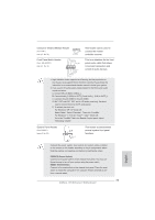
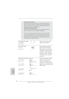
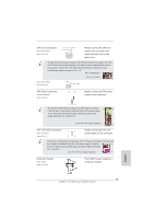
Consumer Infrared Module Header (4-pin CIR1) (see p.2 No. 25) 1 GND IRTX IRRX ATX+5VSB This header can be used to connect the remote controller receiver. Front Panel Audio Header (9-pin HD_AUDIO1) (see p.2 No. 32) GND PRESENCE# MIC_RET OUT_RET 1 OUT2_L J_SENSE OUT2_R MIC2_R MIC2_L This is an interface for the front panel audio cable that allows convenient connection and control of audio devices. 1. High Definition Audio supports Jack Sensing, but the panel wire on the chassis must support HDA to function correctly. Please follow the instruction in our manual and chassis manual to install your system. 2. If you use AC'97 audio panel, please install it to the front panel audio header as below: A. Connect Mic_IN (MIC) to MIC2_L. B. Connect Audio_R (RIN) to OUT2_R and Audio_L (LIN) to OUT2_L. C. Connect Ground (GND) to Ground (GND). D. MIC_RET and OUT_RET are for HD audio panel only. You don't need to connect them for AC'97 audio panel. E. To activate the front mic. For Windows® XP / XP 64-bit OS: Select "Mixer". Select "Recorder". Then click "FrontMic". For Windows® 7 / 7 64-bit / VistaTM / VistaTM 64-bit OS: Go to the "FrontMic" Tab in the Realtek Control panel. Adjust "Recording Volume". System Panel Header (9-pin PANEL1) (see p.2 No. 23) This header accommodates several system front panel functions. English Connect the power switch, reset switch and system status indicator on the chassis to this header according to the pin assignments below. Note the positive and negative pins before connecting the cables. PWRBTN (Power Switch): Connect to the power switch on the chassis front panel. You may configure the way to turn off your system using the power switch. RESET (Reset Switch): Connect to the reset switch on the chassis front panel. Press the reset switch to restart the computer if the computer freezes and fails to perform a normal restart. 23 ASRock 970 Extreme3 Motherboard
-
 1
1 -
2
-
3
-
4
-
5
-
6
-
7
-
8
-
9
-
10
-
11
-
12
-
13
-
14
-
15
-
16
-
17
-
 18
18 -
 19
19 -
 20
20 -
 21
21 -
 22
22 -
 23
23 -
 24
24 -
 25
25 -
 26
26 -
 27
27 -
 28
28 -
29
-
30
-
31
-
32
-
33
-
34
-
35
-
36
-
37
-
38
-
39
-
40
-
41
-
42
-
43
-
44
-
45
-
46
-
47
-
48
-
49
-
50
-
51
-
52
-
53
-
54
-
55
-
56
-
57
-
58
-
59
-
60
-
61
-
62
-
63
-
64
-
65
-
66
-
67
-
68
-
69
-
70
-
71
-
72
-
73
-
74
-
75
-
76
-
77
-
78
-
79
-
80
-
81
-
82
-
83
-
84
-
85
-
86
-
87
-
88
-
89
-
90
-
91
-
92
-
93
-
94
-
95
-
96
-
97
-
98
-
99
-
100
-
101
-
102
-
103
-
104
-
105
-
106
-
107
-
108
-
109
-
110
-
111
-
112
-
113
-
114
-
115
-
116
-
117
-
118
-
119
-
120
-
121
-
122
-
123
-
124
-
125
-
126
-
127
-
128
-
129
-
130
-
131
-
132
-
133
-
134
-
135
-
136
-
137
-
138
-
139
-
140
-
141
-
142
-
143
-
144
-
145
-
146
-
147
-
148
-
149
-
150
-
151
-
152
-
153
-
154
-
155
-
156
-
157
-
158
-
159
-
160
-
161
-
162
-
163
-
164
-
165
-
166
-
167
-
168
-
169
-
170
-
171
-
172
-
173
-
174
-
175
-
176
 |
 |
