ASRock 990FX Extreme6 Quick Installation Guide
ASRock 990FX Extreme6 Manual
 |
View all ASRock 990FX Extreme6 manuals
Add to My Manuals
Save this manual to your list of manuals |
ASRock 990FX Extreme6 manual content summary:
- ASRock 990FX Extreme6 | Quick Installation Guide - Page 1
change without notice, and should not be constructed as a commitment by ASRock. ASRock assumes no responsibility for any errors or omissions that may appear in CALIFORNIA, USA ONLY he Lithium battery adopted on this motherboard contains Perchlorate, a toxic substance controlled in Perchlorate Best - ASRock 990FX Extreme6 | Quick Installation Guide - Page 2
Manufactured under license under U.S. Patent Nos: 5,956,674; 5,974,380; 6,487,535; 7,003,467 & other U.S. and worldwide patents issued & pending. DTS, the Symbol, & DTS and the Symbol together is a registered trademark & DTS Connect, DTS Interactive, DTS Neo:PC are trademarks of DTS, Inc. Product - ASRock 990FX Extreme6 | Quick Installation Guide - Page 3
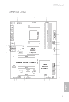
990FX Extreme6 Motherboard Layout 12 34 56 PS2 Mouse PS2 Keyboard USB 2.0 T: USB0 B: USB1 USB 3.0 T: USB1 B: USB2 USB 3.0 T: USB3 B: USB4 USB 2.0 T: USB2 B: USB3 CHA_FAN2 ATX12V1 eSATA USB 2.0 T: USB4 B: - ASRock 990FX Extreme6 | Quick Installation Guide - Page 4
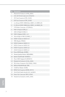
No. Description 1 Chassis Fan Connector (CHA_FAN2) 2 ATX 12V Power Connector (ATX12V1) 3 CPU Fan Connector (CPU_FAN1) 4 CPU Fan Connector (CPU_FAN2) 5 2 x 240-pin DDR3 DIMM Slots (DDR3_A1, DDR3_B1) 6 2 x 240-pin DDR3 DIMM Slots (DDR3_A2, DDR3_B2) 7 ATX Power Connector (ATXPWR1) 8 USB 2.0 Header ( - ASRock 990FX Extreme6 | Quick Installation Guide - Page 5
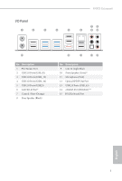
990FX Extreme6 I/O Panel 1 2 3 4 5 79 6 8 10 15 No. Description 1 PS/2 Mouse Port 2 USB 2.0 Ports (USB_01) 3 USB 3.0 Ports (USB3_12) 4 USB 3.0 Ports (USB3_34) 5 USB 2.0 Ports (USB23) 6 LAN RJ-45 Port* 7 - ASRock 990FX Extreme6 | Quick Installation Guide - Page 6
use the Rear Speaker, Central/ Bass, and Front Speaker, or select "Realtek HDA Audio 2nd output" to use the front panel audio. *** he eSATA3 port supports SATA Gen3 in cable 1M. he eSATA3 port is shared with M.2_SSD (NGFF - ASRock 990FX Extreme6 | Quick Installation Guide - Page 7
ind the latest VGA cards and CPU support list on ASRock's website as well. ASRock website http://www.asrock.com. 1.1 Package Contents • ASRock 990FX Extreme6 Motherboard (ATX Form Factor) • ASRock 990FX Extreme6 Quick Installation Guide • ASRock 990FX Extreme6 Support CD • 4 x Serial ATA (SATA) Data - ASRock 990FX Extreme6 | Quick Installation Guide - Page 8
design • 8 + 2 Power Phase design • Supports CPU up to 220W • Supports AMD's Cool 'n' Quiet Technology • FSB 2600 MHz (5.2 GT/s) • Supports Untied Overclocking Technology • Supports Hyper-Transport 3.0 (HT 3.0) Technology Chipset • Northbridge: AMD 990FX • Southbridge: AMD SB950 Memory • Dual - ASRock 990FX Extreme6 | Quick Installation Guide - Page 9
990FX Extreme6 • 15μ Gold Contact in VGA PCIe Slots (PCIE2/PCIE3) Audio • 7.1 CH HD Audio with Content Protection (Realtek ALC1150 Audio Codec) • Premium Blu-ray Audio Support • Supports Purity SoundTM 2 - Nichicon Fine Gold Series Audio Caps - 115dB SNR DAC with Diferential Ampliier - TI® NE5532 - ASRock 990FX Extreme6 | Quick Installation Guide - Page 10
by Etron EJ188 (Supports 2 USB 3.0 ports) (Supports ESD Protection (ASRock Full Spike Protection)) • 32Mb AMI UEFI Legal BIOS with with GUI support • Supports "Plug and Play" • ACPI 1.1 Compliant wake up events • Supports jumperfree • SMBIOS 2.3.1 support • CPU, DRAM, NB, HT, CPU VDDA, PCIE VDDA - ASRock 990FX Extreme6 | Quick Installation Guide - Page 11
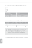
overclocking. 1. Whether 2450/2100MHz memory speed is supported depends on the AM3/AM3+ CPU you adopt. If you want to adopt DDR3 2450/2100 memory module on this motherboard, please refer to the memory support list on our website for the compatible memory modules. ASRock website: http://www.asrock - ASRock 990FX Extreme6 | Quick Installation Guide - Page 12
2 Installation his is an ATX form factor motherboard. Before you install the motherboard, study the coniguration of your chassis to ensure that the motherboard its into it. Pre-installation Precautions Take note of the following precautions before you install motherboard components or change any - ASRock 990FX Extreme6 | Quick Installation Guide - Page 13
2.1 Installing the CPU Unplug all power cables before installing the CPU. 1 2 - ASRock 990FX Extreme6 | Quick Installation Guide - Page 14
3 12 English - ASRock 990FX Extreme6 | Quick Installation Guide - Page 15
990FX Extreme6 2.2 Installing the CPU Fan and Heatsink Ater you install the CPU into this motherboard, it is necessary to install a larger heatsink and cooling fan to dissipate heat. You also need to spray thermal grease between the CPU and the heatsink to improve heat dissipation. Make sure that - ASRock 990FX Extreme6 | Quick Installation Guide - Page 16
2.3 Installing Memory Modules (DIMM) his motherboard provides four 240-pin DDR3 (Double Data Rate 3) DIMM slots, and supports Dual Channel Memory Technology. 1. For dual channel coniguration, you always need to install identical (the same brand, speed, size and chip-type) DDR3 DIMM pairs. 2. - ASRock 990FX Extreme6 | Quick Installation Guide - Page 17
990FX Extreme6 1 2 3 15 English - ASRock 990FX Extreme6 | Quick Installation Guide - Page 18
Express Slots) here are 5 PCI Express slots on the motherboard. Before installing an expansion card, please make sure that the For a better thermal environment, please connect a chassis fan to the motherboard's chassis fan connector (CHA_FAN1, CHA_FAN2 or CHA_FAN3) when using multiple graphics cards - ASRock 990FX Extreme6 | Quick Installation Guide - Page 19
990FX Extreme6 2.5 Jumpers Setup he illustration shows how jumpers are setup. When the jumper 5 seconds. However, please do not clear the CMOS right ater you update the BIOS. If you need to clear the CMOS when you just inish updating the BIOS, you must boot up the system irst, and then shut it down - ASRock 990FX Extreme6 | Quick Installation Guide - Page 20
place jumper caps over these headers and connectors. Placing jumper caps over the headers and connectors will cause permanent damage to the motherboard. System Panel Header (9-pin PANEL1) (see p.1, No. 20) PLED+ PLEDPWRBTN# GND 1 GND RESET# GND HDLEDHDLED+ Connect the power switch, reset switch - ASRock 990FX Extreme6 | Quick Installation Guide - Page 21
990FX Extreme6 Power LED Header (3-pin PLED1) (see p.1, No. 18) 1 PLEDPLED+ PLED+ GND P+ PUSB_PWR Besides six USB 2.0 ports on the I/O panel, there are two headers on this motherboard. Each USB 2.0 header can support two ports. USB 3.0 Headers (19-pin USB3_5_6) (see p.1, No. 10) (USB3_7) (see - ASRock 990FX Extreme6 | Quick Installation Guide - Page 22
for connecting audio devices to the front audio panel. 1. High Deinition Audio supports Jack Sensing, but the panel wire on the chassis must support HDA to function correctly. Please follow the instructions in our manual and chassis manual to install your system. 2. If you use an AC'97 audio panel - ASRock 990FX Extreme6 | Quick Installation Guide - Page 23
990FX Extreme6 CPU Fan Connectors (4-pin CPU_FAN1) (see p.1, No. 3) (3-pin CPU_FAN2) (see p.1, No. 4) FAN_SPEED_CONTROL CPU_FAN_SPEED +12V GND 1 2 3 4 GND +12V CPU_FAN_SPEED his motherboard provides a 4-Pin CPU fan (Quiet Fan) connector. If you plan to connect a 3-Pin CPU fan, please connect it - ASRock 990FX Extreme6 | Quick Installation Guide - Page 24
Serial Port Header (9-pin COM1) (see p.1, No. 25) RRXD1 DDTR#1 DDSR#1 CCTS#1 1 RRI#1 RRTS#1 GND TTXD1 DDCD#1 his COM1 header supports a serial port module. SPDIF Out Connector (2-pin SPDIF_OUT1) (see p.1, No. 26) 1 GND SPDIFOUT Please connect the SPDIF_OUT connector of a HDMI VGA card to this - ASRock 990FX Extreme6 | Quick Installation Guide - Page 25
VGA-Karten und Prozessoren auf der ASRock-Webseite: ASRock-Webseite http://www.asrock.com. 1.1 Lieferumfang • ASRock 990FX Extreme6-Motherboard (ATX-Formfaktor) • ASRock 990FX Extreme6-Schnellinstallationsanleitung • ASRock 990FX Extreme6-Support-CD • 4 x Serial-ATA- (SATA) Datenkabel (optional - ASRock 990FX Extreme6 | Quick Installation Guide - Page 26
Erweitertes 8 + 2-Stromphasendesign • Unterstützt CPU bis 220W • Unterstützt Cool 'n' QuietTM-Technologie von AMD • FSB 2600 MHz (5.2 GT/s) • Unterstützt Untied-Übertaktungstechnologie • Unterstützt Hyper-Transport- 3.0 Technologie (HT 3.0) • Northbridge: AMD 990FX • Southbridge: AMD SB950 Speicher - ASRock 990FX Extreme6 | Quick Installation Guide - Page 27
990FX Extreme6 Audio LAN Rückblende, E/A • 7.1-Kanal-HD-Audio mit Inhaltsschutz (Realtek ALC1150Audiocodec) Unterstützt Wake-On-LAN • Unterstützt Blitzschutz/Schutz gegen elektrostatische Entla- dung (ASRock Full Spike Protection) • Unterstützt energieeizientes Ethernet 802.3az • Unterstützt PXE - ASRock 990FX Extreme6 | Quick Installation Guide - Page 28
1 x TPM-Stitleiste • 1 x Betrieb-LED-Stitleiste • 2 x CPU-Lüteranschlüsse (1 x 4-polig, 1 x 3-polig) • 3 x x Netzteillüteranschluss (3-polig) • 1 x 24-poliger ATX-Netzanschluss • 1 x 8-poliger 12-V-Netzanschluss (hochdichter Netzanschluss ASRock Full Spike Protection)) • 32-Mb-AMI-UEFI-Legal-BIOS - ASRock 990FX Extreme6 | Quick Installation Guide - Page 29
990FX Extreme6 Hardwareüberwachung Betriebssystem Zertiizierungen • CPU-/Gehäusetemperaturerkennung • CPU/Gehäuse/Netzteil-Lütertachometer • Lautloser CPU-/Gehäuselüter (ermöglicht automatische Anpassung der Geschwindigkeit des Gehäuselüters über die CPU-Temperatur) • CPU/Gehäuselüter- - ASRock 990FX Extreme6 | Quick Installation Guide - Page 30
3 an CLRCMOS1 5 Sekunden lang mit einer Jumper-Kappe kurz. Löschen Sie den CMOS jedoch nicht direkt nach der BIOS-Aktualisierung. Falls Sie den CMOS direkt nach Abschluss der BIOS-Aktualisierung löschen müssen, starten Sie das System zunächst; fahren Sie es dann vor der CMOS-Löschung herunter. Bitte - ASRock 990FX Extreme6 | Quick Installation Guide - Page 31
990FX Extreme6 1.4 Integrierte Stiftleisten und Anschlüsse Integrierte Stitleisten und Anschlüsse sind KEINE Jumper. Bringen Sie KEINE Jumper-Kappen an diesen Stitleisten und Anschlüssen an. Durch Anbringen von Jumper-Kappen an diesen Stitleisten und Anschlüssen können Sie das Motherboard dauerhat - ASRock 990FX Extreme6 | Quick Installation Guide - Page 32
DUMMY 1 GND P+ PUSB_PWR Neben sechs USB 2.0-Ports an der E/A-Blende beinden sich zwei Stitleisten an diesem Motherboard. Jede USB 2.0-Stitleiste kann zwei Ports unterstützen. Vbus IntA_PA_SSRXIntA_PA_SSRX+ GND IntA_PA_SSTXIntA_PA_SSTX+ GND IntA_PA_DIntA_PA_D+ Vbus IntA_PB_SSRXIntA_PB_SSRX+ GND - ASRock 990FX Extreme6 | Quick Installation Guide - Page 33
990FX Extreme6 Audiostitleiste (Frontblende) (9-polig, HD_AUDIO1) (siehe S. 1, Nr. 27) GND PRESENCE# MIC_RET OUT_RET 1 OUT2_L J_SENSE OUT2_R MIC2_R MIC2_L Diese Stitleiste dient dem Anschließen von Audiogeräten - ASRock 990FX Extreme6 | Quick Installation Guide - Page 34
bietet einen 4-poligen CPULüteranschluss (lautloser Lüter). Falls Sie einen 3-poligen CPU-Lüter anschließen möchten, verbinden Sie ihn bitte mit Kontakt 1 bis 3. 12 24 1 13 Dieses Motherboard bietet einen 24-poligen ATX-Netzanschluss. Bitte schließen Sie es zur Nutzung eines 20-poligen - ASRock 990FX Extreme6 | Quick Installation Guide - Page 35
990FX Extreme6 Serieller-Port-Stitleiste (9-polig, COM1) (siehe S. 1, Nr. 25) SPDIF-Ausgang (2-polig, SPDIF_OUT1) (siehe S. 1, Nr. 26) RRXD1 DDTR#1 DDSR#1 CCTS#1 1 RRI#1 RRTS#1 GND TTXD1 DDCD#1 1 GND - ASRock 990FX Extreme6 | Quick Installation Guide - Page 36
Carte mère ASRock 990FX Extreme6 (facteur de forme ATX) • Guide d'installation rapide ASRock 990FX Extreme6 • CD d'assistance ASRock 990FX Extreme6 • 4 x câbles de données Serial ATA (SATA) (Optionnel) • 1 x panneau de protection E/S • 1 x carte ASRock SLI_Bridge_2S • 1 x M.2_SSD (NGFF) Socket 3 Vis - ASRock 990FX Extreme6 | Quick Installation Guide - Page 37
8 + 2 Power Phase • Supporte les processeurs jusqu'à 220W • Supporte la technologie Cool 'n' QuietTM d'AMD • FSB 2600 MHz (5.2 GT/s) • Prend en charge la technologie Untied Overclocking • Prise en charge de la technologie Hyper Transport 3.0 (HT 3.0) • Northbridge: AMD 990FX • Southbridge: AMD SB950 - ASRock 990FX Extreme6 | Quick Installation Guide - Page 38
• Prend en charge la fonction Wake-On-LAN • Protection contre les orages/décharges électrostatiques (Pro- tection complète contre les pics ASRock) • Prend en charge la fonction d'économie d'énergie Ethernet 802,3az • Prend en charge PXE • 1 x port souris PS/2 • 1 x port clavier PS/2 • 1 x port - ASRock 990FX Extreme6 | Quick Installation Guide - Page 39
990FX Extreme6 Stockage Connectique Caractéristiques du BIOS • 5 x connecteurs SATA3 6,0 Go/s, compatibles RAID (RAID 0, RAID 1, RAID 0+1, JBOD et RAID 5), NCQ, AHCI et « Hot Plug » • 1 x M.2_SSD (NGFF) Socket ATX ASRock ASRock)) • BIOS UEFI AMI 32Mo avec prise en charge interface graphique • Support - ASRock 990FX Extreme6 | Quick Installation Guide - Page 40
rils. Nous ne pourrons en aucun cas être tenus pour responsables des dommages éventuels provoqués par l'overclocking. 1. La prise en charge de fréquences de mémoire de 2450/2100MHz dépend du CPU AM3/AM3+ que vous choisissez. Si vous choisissez des barrettes de mémoire DDR3 2450/2100 sur cette carte - ASRock 990FX Extreme6 | Quick Installation Guide - Page 41
990FX Extreme6 1.3 Coniguration des cavaliers (jumpers) L'illustration ci-dessous vous renseigne efacez pas la CMOS immédiatement après avoir mis à jour le BIOS. Si vous avez besoin d'efacer les données CMOS après une mise à jour du BIOS, vous devez tout d'abord redémarrer le système, puis l'éteindre - ASRock 990FX Extreme6 | Quick Installation Guide - Page 42
1.4 Embases et connecteurs de la carte mère Les embases et connecteurs situés sur la carte NE SONT PAS des cavaliers. Ne placez JAMAIS de capuchons de cavaliers sur ces embases ou connecteurs. Placer un capuchon de cavalier sur ces embases ou connecteurs endommagera irrémédiablement votre carte mère - ASRock 990FX Extreme6 | Quick Installation Guide - Page 43
990FX Extreme6 Embase LED d'alimentation (PLED1 à 3 broches) (voir p.1, No. 18) 1 PLEDPLED+ PLED+ Connecteurs Serial ATA3 (SATA3_1: (voir p.1, No. 17) (SATA3_2: (voir p.1, No. 16) (SATA3_3: voir p.1, No. 14) ( - ASRock 990FX Extreme6 | Quick Installation Guide - Page 44
Jack Sensing (détection de la iche), mais le panneau grillagé du châssis doit être compatible avec la HDA pour fonctionner correctement. Veuillez suivre les instructions igurant dans notre manuel et dans le manuel du châssis pour installer votre système. 2. Si vous utilisez un panneau audio AC'97 - ASRock 990FX Extreme6 | Quick Installation Guide - Page 45
990FX Extreme6 Connecteurs du ventilateur du processeur (CPU_FAN1 à 4 broches) (voir p.1, No. 3) (CPU_FAN2 à 3 broches) (voir p.1, de processeur à 3 broches, veuillez le brancher sur la Broche 1-3. Connecteur d'alimentation ATX (ATXPWR1 à 24 broches) (voir p.1, No. 7) 12 24 1 13 Cette - ASRock 990FX Extreme6 | Quick Installation Guide - Page 46
Embase pour port série (COM1 à 9 broches) (voir p.1, No. 25) Connecteur sortie SPDIF (SPDIF_OUT1 à 2 broches) (voir p.1, No. 26) RRXD1 DDTR#1 DDSR#1 CCTS#1 1 RRI#1 RRTS#1 GND TTXD1 DDCD#1 1 GND SPDIFOUT Cette embase COM1 prend en charge un module de port série. Veuillez brancher le connecteur - ASRock 990FX Extreme6 | Quick Installation Guide - Page 47
e di supporto di CPU anche sul sito Web di ASRock. Sito Web di ASRock http://www.asrock.com. 1.1 Contenuto della confezione • Scheda madre 990FX Extreme6 ASRock (fattore di forma ATX) • Guida rapida di installazione 990FX Extreme6 ASRock • CD di supporto 990FX Extreme6 ASRock • 4 x cavi dati Serial - ASRock 990FX Extreme6 | Quick Installation Guide - Page 48
con alimentazione 8 + 2 avanzata • Supporta CPU ino a 220 W • Supporto tecnologia AMD Cool 'n' QuietTM • FSB 2600 MHz (5.2 GT/s) • Supporta la tecnologia overclocking "slegata" • Supporta la tecnologia Hyper-Transport 3.0 (HT 3.0) Chipset • Northbridge: AMD 990FX • Southbridge: AMD SB950 Italiano - ASRock 990FX Extreme6 | Quick Installation Guide - Page 49
990FX Extreme6 Audio LAN I/O pannello posteriore • Supporta NVIDIA® Quad SLITMe SLITM • Contatti Supporta Wake-On-LAN • Supporto la protezione da fulmini/scariche elettrostatiche (ESD) (protezione completa ASRock dai picchi di corrente) • Supporta Energy Eicient Ethernet 802.3az • Supporta PXE • 1 - ASRock 990FX Extreme6 | Quick Installation Guide - Page 50
NGFF) Socket 3 condiviso con il connettore eSATA3) • 1 x header IR • 1 x header porta COM • 1 x header TPM • 1 x header LED di alimentazione • 2 x connettori ventola CPU (1 x scariche elettrostatiche (ESD) (protezione completa ASRock dai picchi di corrente)) • BIOS legale 32Mb AMI UEFI con supporto - ASRock 990FX Extreme6 | Quick Installation Guide - Page 51
o meno, dipende dagli AM3/AM3+ CPU utilizzati. Se si desidera adottare il modulo di memoria DDR3 2450/2100 su questa scheda madre, fare riferimento all'elenco delle memorie supportate nel nostro sito web per scoprire quali sono i moduli compatibili. Sito web ASRock http://www.asrock.com 2. A causa - ASRock 990FX Extreme6 | Quick Installation Guide - Page 52
il pin2 e il pin3 su CLRCMOS1 per 5 secondi. Tuttavia, non azzerare la CMOS subito dopo aver aggiornato il BIOS. Se è necessario azzerare la CMOS dopo l'aggiornamento del BIOS, è necessario riavviare prima il sistema e in seguito spegnerlo prima di eseguire l'operazione di azzeramento della CMOS. La - ASRock 990FX Extreme6 | Quick Installation Guide - Page 53
990FX Extreme6 1.4 Header e connettori sulla scheda Gli header e i connettori sulla scheda NON sono jumper. NON posizionare cappucci del jumper su questi header e connettori. Il posizionamento di cappucci - ASRock 990FX Extreme6 | Quick Installation Guide - Page 54
Header LED di alimentazione (PLED1 a 3 pin) (vedere pag. 1, n. 18) Connettori Serial ATA3 (SATA3_1: vedere pag. 1, n. 17) (SATA3_2: vedere pag. 1, n. 16) (SATA3_3: vedere pag.1, n. 14) (SATA3_4: vedere pag.1, n. 15) (SATA3_5: vedere pag.1, n. 12) SATA3_1 SATA3_3 SATA3_5 SATA3_2 SATA3_4 1 PLEDPLED+ - ASRock 990FX Extreme6 | Quick Installation Guide - Page 55
990FX Extreme6 Header audio pannello anteriore (AUDIO1_HD a 9 pin) (vedere pag. 1, n. 27) GND PRESENCE deve supportare HDA per funzionare correttamente. Seguire le istruzioni presenti nel nostro manuale e nel manuale dello chassis per installare il sistema. 2. Se si utilizza un pannello audio - ASRock 990FX Extreme6 | Quick Installation Guide - Page 56
Questa scheda madre è dotata di un connettore per la ventola della CPU (Ventola silenziosa) a 4 pin. Se si decide di collegare una ventola della CPU a 3 pin, collegarla al pin 1-3. Connettore di alimentazione ATX (ATXPWR1 a 24 pin) (vedere pag. 1, n. 7) 12 24 1 13 Questa scheda madre - ASRock 990FX Extreme6 | Quick Installation Guide - Page 57
990FX Extreme6 Header porta seriale (COM1 a 9 pin) (vedere pag. 1, n. 25) Connettore uscita SPDIF (SPDIF_OUT1 a 2 pin) (vedere pag. 1, n. 26) RRXD1 DDTR#1 DDSR#1 CCTS#1 1 RRI#1 RRTS#1 GND TTXD1 DDCD#1 1 - ASRock 990FX Extreme6 | Quick Installation Guide - Page 58
de compatibilidad de la CPU, en el sitio web de ASRock. Sitio web de ASRock http://www.asrock.com. 1.1 Contenido del paquete • Placa base ASRock 990FX Extreme6 (Factor de forma ATX) • Guía de instalación rápida de ASRock 990FX Extreme6 • CD de soporte de ASRock 990FX Extreme6 • 4 cables de datos - ASRock 990FX Extreme6 | Quick Installation Guide - Page 59
990FX Extreme6 1.2 Especiicaciones Plataforma • Factor de forma ATX • Tapas de platino de Nichicon 12K (Condensadores de polímero conductor, de alta calidad, 100% fabricados en Japón) • PCB de ibra de vidrio de alta densidad CPU • Compatibilidad con procesadores con conector AM3 Extreme Memory - ASRock 990FX Extreme6 | Quick Installation Guide - Page 60
en internet Wake On Qualcomm® Atheros® • Compatible con Wake-On-LAN • Compatible con protección contra rayos y electricidad elec- trostática (protección ASRock Full Spike) • Compatible con Ethernet de consumo eiciente de energía 802.3az • Compatible con PXE • 1 puerto de ratón PS/2 • 1 puerto de - ASRock 990FX Extreme6 | Quick Installation Guide - Page 61
990FX Extreme6 Almacenamiento Conectores Características del BIOS • Los 5 LED de alimentación • 2 conectores de ventilador de la CPU (1 de 4 pines y 1 de 3 pines) • 3 pines) • 1 conector de alimentación ATX de 24 pines • 1 conector de alimentación (protección ASRock Full Spike)) • BIOS Legal UEFI - ASRock 990FX Extreme6 | Quick Installation Guide - Page 62
temperatura de la CPU) • Control multivelocidad del ventilador de la CPU/Chasis • Control del voltaje: +12V, +5V, +3,3V, CPU Vcore • Compatible asrock.com Tenga en cuenta que existen ciertos riesgos relacionados con el overclocking (sobreaceleración), incluyendo el ajuste de la coniguración del BIOS - ASRock 990FX Extreme6 | Quick Installation Guide - Page 63
990FX Extreme6 1.3 Instalación de los puentes La instalación muestra cómo deben embargo, no borre el CMOS justo después de que haya actualizado el BIOS. Si necesita borrar el CMOS cuando acabe de actualizar el BIOS, deberá arrancar el sistema primero y, a continuación, deberá apagarlo antes - ASRock 990FX Extreme6 | Quick Installation Guide - Page 64
1.4 Conectores y cabezales incorporados Los cabezales y conectores incorporados NO son puentes. NO coloque tapas de puente sobre estos cabezales y conectores. Si coloca tapas de puente sobre los cabezales y conectores dañará de forma permanente la placa base. Cabezal del panel del sistema (PANEL1 - ASRock 990FX Extreme6 | Quick Installation Guide - Page 65
SATA3_1 SATA3_3 SATA3_5 SATA3_2 SATA3_4 Español 990FX Extreme6 Cabezal de indicador LED de alimentación (PLED1 de 3 pines) (consulte la pág.1, N.º 18) 1 PLEDPLED+ PLED+ Conectores Serie ATA3 (SATA3_1: consulte la pág.1, N.º 17) (SATA3_2: consulte la pág.1, N.º 16) ( - ASRock 990FX Extreme6 | Quick Installation Guide - Page 66
, el cable del panel del chasis deberá ser compatible con HDA para que pueda funcionar correctamente. Siga las instrucciones que se indican en nuestro manual y en el manual del chasis para instalar su sistema. 2. Si utiliza un panel de audio AC'97, instálelo en el cabezal de audio del panel frontal - ASRock 990FX Extreme6 | Quick Installation Guide - Page 67
990FX Extreme6 Conectores del ventilador de la CPU (CPU_FAN1 de 4 pines) (consulte la pág.1, N.º 3) (CPU_FAN2 de 3 pines) ( 2) 5 Esta placa base contiene un conector de alimentación ATX de 12V 1 y 8 pines. Para utilizar una toma de alimentación ATX de 4 pines, conéctela en los Pines del 1 - ASRock 990FX Extreme6 | Quick Installation Guide - Page 68
Cabezal de puerto serie (COM1 de 9 pines) (consulte la pág.1, N.º 25) RRXD1 DDTR#1 DDSR#1 CCTS#1 1 RRI#1 RRTS#1 GND TTXD1 DDCD#1 Este cabezal COM1 admite un módulo de puerto serie. Conector de salida SPDIF (SPDIF_OUT1 de 2 pines) (consulte la pág.1, N.º 26) 1 GND SPDIFOUT Conecte el conector - ASRock 990FX Extreme6 | Quick Installation Guide - Page 69
990FX Extreme6 1 ASRock 990FX Extreme6 ASRock ASRock BIOS ASRock ASRock VGA ASRock http://www.asrock.com. 1.1 ASRock 990FX Extreme6 ATX ASRock 990FX Extreme6 ASRock 990FX Extreme6 • 4 Serial ATA (SATA 1 1 x карта ASRock SLI_Bridge_2S • 1 x M.2_SSD (NGFF 3 67 - ASRock 990FX Extreme6 | Quick Installation Guide - Page 70
Socket AM3 Socket AM3 AMD PhenomTM II X6 / X4 / X3 / X2 920 / 940) / Athlon II X4 / X3 / X2 / Sempron UCC (Unlock CPU Core DigiPower Advanced 8 + 2 Power Phase Design 220 AMD Cool 'n' QuietTM • FSB 2600 MHz (5.2 GT/s Untied Overclocking Hyper-Transport 3.0 (HT 3.0) AMD 990FX - ASRock 990FX Extreme6 | Quick Installation Guide - Page 71
990FX Extreme6 Аудио ЛВС • 7.1 HD Audio Realtek ALC1150) Premium Blu-ray Audio Purity 802.3az PXE • 1 x PS/2 1 x PS/2 1 x SPDIF • 6 x USB 2.0 ASRock Full Spike Protection) • 4 x USB 3.0 ASMedia ASRock Full Spike Protection) • 1 x eSATA3 • 1 x RJ-45 ACT/LINK и МИД SPEED HD - ASRock 990FX Extreme6 | Quick Installation Guide - Page 72
Full Spike Protection) • 1 USB 3.0 типа A ASRock Full Spike Protection) • 1 x Etron EJ188 USB 3.0 2 USB 3.0 ASRock Full Spike Protection) • 32 Мб AMI UEFI Legal BIOS Plug and Play ACPI 1.1 SMBIOS 2.3.1 DRAM, NB, HT, CPU VDDA, PCIE VDDA, CPU NB 12 В, +5 В, +3,3 В, ЦП Vcore 70 - ASRock 990FX Extreme6 | Quick Installation Guide - Page 73
990FX Extreme6 ОС • Microsot® Windows® 8.1 32 8.1 64 8 32 8 64 7 32 7 64 • FCC, CE, WHQL ErP/EuP ErP/EuP) http://www.asrock.com BIOS Untied Overclocking Technology 1 2450/2100 AM3/AM3 DDR3 2450/2100 ASRock http://www.asrock.com 2 4 Windows® 8.1 / 8 / 7 Windows® OS с - ASRock 990FX Extreme6 | Quick Installation Guide - Page 74
1.3 3 1 и 2 CMOS (CLRCMOS1 1, № 21) CMOS CLRCMOS1 CMOS 15 2 и 3 на CLRCMOS1 на 15 CMOS BIOS CMOS BIOS CMOS CMOS. 72 - ASRock 990FX Extreme6 | Quick Installation Guide - Page 75
990FX Extreme6 1.4 9 PANEL1 1, № 20) PLED+ PLEDPWRBTN# GND 1 GND RESET# GND HDLEDHDLED+ PWRBTN RESET PLED S1/S3 S4 S5 HDLED 73 - ASRock 990FX Extreme6 | Quick Installation Guide - Page 76
3 PLED1 1, № 18) 1 PLEDPLED+ PLED+ Serial ATA3 (SATA3_1 1, № 17) (SATA3_2 1, № 16) (SATA3_3 1, № 14) (SATA3_4 1, № 15) (SATA3_5 1, № 12) SATA3_1 SATA3_3 SATA3_5 SATA3_2 SATA3_4 SATA3 SATA 6,0 Гб/с. USB 2.0. (9 USB6_7 1, № 9) (9 USB8_9 1, № 8) USB_PWR PP+ GND DUMMY 1 - ASRock 990FX Extreme6 | Quick Installation Guide - Page 77
990FX Extreme6 9 HD_ AUDIO1 1, № 27) GND PRESENCE# MIC_RET OUT_RET 1 OUT2_L J_SENSE OUT2_R MIC2_R MIC2_L 1 HDA 2 AC'97 A Mic_IN (MIC) к MIC2_L. B Audio_R (RIN) к OUT2_R, Audio_L (LIN) к OUT2_L. C GND - ASRock 990FX Extreme6 | Quick Installation Guide - Page 78
1, № 2) PCIe (4 SLI/ XFIRE_PWR1 1, № 23) FAN_SPEED_CONTROL CPU_FAN_SPEED +12V GND 1 2 3 4 GND +12V CPU_FAN_SPEED 4 3 1-3. 12 24 1 13 24 20 ATX 1 13. 8 5 8 4 1 12 4 ATX, 1 5. 5 IR1 1, № 24) IRTX +5VSB DUMMY 1 GND IRRX 76 - ASRock 990FX Extreme6 | Quick Installation Guide - Page 79
990FX Extreme6 9 COM1 1, № 25) RRXD1 DDTR#1 DDSR#1 CCTS#1 1 RRI#1 RRTS#1 GND TTXD1 DDCD#1 COM1 SPDIF (2 SPDIF_ OUT1 1, № 26) 1 GND SPDIFOUT SPDIF_OUT карты HDMI VGA 17 TPMS1 1, № 13) - ASRock 990FX Extreme6 | Quick Installation Guide - Page 80
• Placa principal ASRock 990FX Extreme6 (Formato ATX) • Guia de instalação rápida da ASRock 990FX Extreme6 • CD de suporte da ASRock 990FX Extreme6 • 4 x Cabos de dados Serial ATA (SATA) (Opcional) • 1 x Painel de E/S • 1 x Placa Bridge_SLI_2S ASRock • 1 x Parafuso M.2_SSD (NGFF) Socket 3 78 - ASRock 990FX Extreme6 | Quick Installation Guide - Page 81
990FX Extreme6 Português 1.2 Especiicações Plataforma • Formato ATX • Capas de Platina de Nichicon 12K (Condensadores de polímeros condutores de alta qualidade 100% fabricados no Japão) • Tecido de Vidro de Alta densidade PCB CPU • Suporte para processadores AM3 • Suporta Extreme Memory Proile - ASRock 990FX Extreme6 | Quick Installation Guide - Page 82
a tecnologia Qualcomm® Atheros® Security Wake On Internet • Suporta Wake-On-LAN • Suporta Proteção contra Relâmpago/EDS (Proteção Total Contra Picos ASRock) • Suporta IEEE 802.3az • Suporta PXE • 1 x Porta PS/2 para rato • 1 x Porta PS/2 para teclado • 1 x Porta de saída SPDIF óptica • 6 x portas - ASRock 990FX Extreme6 | Quick Installation Guide - Page 83
990FX Extreme6 Armazenamento Conector Funcionalidades da BIOS • 5 x conectores SATA3 a 6,0 Gb/s, com suporte para RAID (RAID 0, RAID 1, RAID 0+1, JBOD e RAID 5), NCQ, AHCI e "Hot Plug" • 1 x M.2_SSD (NGFF) Socket 3, suporta módulo M.2 SATA3 6,0 Gb/s e módulo M.2 PCI Express até Gen2 x2 (10 Gb/s) - ASRock 990FX Extreme6 | Quick Installation Guide - Page 84
deverá ser efectuado por sua conta e risco. Não nos responsabilizamos por possíveis danos causados pelo overclocking. 1. O suporte às velocidades 2450/2100MHz de memória depende da CPU AM3/AM3+ adotada. Se você quiser adotar módulos de memória DDR3 2450/2100 nesta placa, por favor veriique - ASRock 990FX Extreme6 | Quick Installation Guide - Page 85
990FX Extreme6 1.3 Coniguração dos jumpers A imagem abaixo ilustra como os jumpers são conigurados. limpe o CMOS logo após ter efectuado a actualização da BIOS. Se precisar de limpar o CMOS logo após ter terminado uma actualização da BIOS, deverá primeiro iniciar o sistema e voltar a encerrá-lo - ASRock 990FX Extreme6 | Quick Installation Guide - Page 86
1.4 Terminais e conectores integrados Os terminais e conectores integrados NÃO são jumpers. NÃO coloque tampas de jumpers sobre estes terminais e conectores. Colocar tampas de jumpers sobre os terminais e conectores irá causar danos permanentes à placa principal. Terminal do painel de sistema ( - ASRock 990FX Extreme6 | Quick Installation Guide - Page 87
SATA3_1 SATA3_3 SATA3_5 SATA3_2 SATA3_4 Português 990FX Extreme6 Conector do LED de alimentação (PLED1 de 3 pinos) (consultar p.1, N.º 18) Conectores ATA3 de série (SATA3_1: consultar p.1, N.º 17) (SATA3_2: consultar p.1, N.º 16) (SATA3_3: consultar p.1, N.º 14) (SATA3_4: consultar p.1, N.º - ASRock 990FX Extreme6 | Quick Installation Guide - Page 88
deinição suporta Detecção de icha, mas o cabo de painel no chassis deverá suportar HDA para funcionar correctamente. Siga as instruções no nosso manual e no manual do chassis para instalar o seu sistema. 2. Se utilizar um painel de áudio AC'97, instale-o no terminal de áudio do painel frontal de - ASRock 990FX Extreme6 | Quick Installation Guide - Page 89
990FX Extreme6 Português Conectores da ventoinha da CPU (CPU_FAN1 de 4 pinos) (consultar p.1, N.º 3) (CPU_FAN2 de 3 pinos) (consultar p.1, N.º 4) Conector de alimentação ATX (ATXPWR1 de 24 pinos) (consultar p.1, N.º 7) Conector de alimentação de 12V ATX (ATX12V1 de 8 pinos) (consultar p.1, N.º 2) - ASRock 990FX Extreme6 | Quick Installation Guide - Page 90
Terminal de porta de série (COM1 de 9 pinos) (consultar p.1, N.º 25) RRXD1 DDTR#1 DDSR#1 CCTS#1 1 RRI#1 RRTS#1 GND TTXD1 DDCD#1 Este terminal COM1 suporta um módulo de porta de série. Conector de saída SPDIF (SPDIF_OUT1 de 2 pinos) (consultar p.1, N.º 26) 1 GND SPDIFOUT Ligue o conector SPDIF_ - ASRock 990FX Extreme6 | Quick Installation Guide - Page 91
ı ve CPU destek listelerini de ASRock'ın web sitesinden bulabilirsiniz. ASRock'ın web sitesi http://www.asrock.com. 1.1 Ambalaj İçeriği • ASRock Fatal1ty 990FX Extreme6 Anakartı (ATX Form Faktörü) • ASRock Fatal1ty 990FX Extreme6 Hızlı Kurulum Kılavuzu • ASRock Fatal1ty 990FX Extreme6 Destek CD - ASRock 990FX Extreme6 | Quick Installation Guide - Page 92
ı Tasarımı • 220W'ye kadar CPU'yu destekler • AMD'nin Cool 'n' QuietTM Teknolojisini Destekler • FSB 2600 MHz (5,2 GT/sn) • Untied Overclocking Teknolojisini destekler • Hyper-Transport 3.0 (HT 3.0) Teknolojisini Destekler Yonga kümesi • Kuzey Köprüsü: AMD 990FX • Güney Köprüsü: AMD SB950 Bellek - ASRock 990FX Extreme6 | Quick Installation Guide - Page 93
990FX Extreme6 • VGA PCIe Yuvasında (PCIE2/PCIE3) 15μ Altın Temas Ses • İçerik (AS- Rock Tam Ani Gerilim Koruması)) • 4 x USB 3.0 Bağlantı Noktası (ASMedia Hub) (ESD Koruması Destekler (ASRock Tam Ani Gerilim Koruması)) • 1 x eSATA3 Bağlayıcısı • LED'e sahip 1 x RJ-45 LAN Bağlantı Noktası ( - ASRock 990FX Extreme6 | Quick Installation Guide - Page 94
• 1 x TPM bağlantısı • 1 x Güç LED bağlantısı • 2 x CPU Fan bağlayıcıları (1 x 4-pin, 1 x 3-pin) • 3 x Kasa ) • 1 x Güç Fanı bağlayıcısı (3-pin) • 1 x 24 pin ATX güç bağlayıcısı • 1 x 8 pin 12V güç bağlayıcısı (Yüksek Yoğ ASRock Tam Ani Gerilim Koruması)) • GUI Desteği ile 32Mb AMI UEFI Legal BIOS - ASRock 990FX Extreme6 | Quick Installation Guide - Page 95
990FX Extreme6 Donanım İzleyici • CPU/Kasa Sıcaklığı Tespiti • CPU/Kasa/Güç Fanı Devirölçer • CPU/Kasa Sessiz Fan (Kasa Fan Hızının CPU Sıcaklığına Göre Otomatik olarak Ayarlanmasını Sağlar) • CPU/Kasa Fanı Çoklu Hız Kontrolü • Voltaj İzleme: +12V, +5V, +3,3V, CPU .asrock.com Lütfen, BIOS ayarlar - ASRock 990FX Extreme6 | Quick Installation Guide - Page 96
, CLRCMOS1 üzerindeki pin2 ve pin3'ü 5 saniye boyunca kısaltmak için bir bağlantı teli kullanın. Ancak, CMOS'u lütfen BIOS'u güncelledikten hemen sonra temizlemeyin. BIOS'u güncelledikten hemen sonra CMOS'u temizlemeniz gerekirse, önce sistemi başlatın ve ardından CMOS temizleme işlemi öncesinde - ASRock 990FX Extreme6 | Quick Installation Guide - Page 97
990FX Extreme6 1.4 Ekli Bağlantılar ve Bağlayıcılar Ekli bağlantılar ve bağlayıcılar bağlantı teli değildir. Bağlantı teli kapaklarını - ASRock 990FX Extreme6 | Quick Installation Guide - Page 98
Türkçe Güç LED Bağlantısı (3-pin PLED1) (bkz. sf.1, No. 18) Seri ATA3 Bağlayıcıları (SATA3_1: bkz. sf.1, No. 17) (SATA3_2: bkz. sf.1, No. 16) (SATA3_3: bkz. sf.1, No. 14) (SATA3_4: bkz. sf.1, No. 15) (SATA3_5: bkz. sf.1, No. 12) SATA3_1 SATA3_3 SATA3_5 SATA3_2 SATA3_4 1 PLEDPLED+ PLED+ Sistemin - ASRock 990FX Extreme6 | Quick Installation Guide - Page 99
990FX Extreme6 Türkçe Ön Panel Ses Bağlantısı (9-pin HD_AUDIO1) (bkz. sf.1, No. 27) GND PRESENCE# MIC_RET OUT_RET 1 OUT2_L J_SENSE OUT2_R MIC2_R MIC2_L Bu bağlantı, ses aygı - ASRock 990FX Extreme6 | Quick Installation Guide - Page 100
+12V GND 1 2 3 4 GND +12V CPU_FAN_SPEED Bu anakart, 4-Pin CPU fan (Sessiz Fan) bağlayıcısı sağlamaktadır. 3-Pin CPU fan bağlamak istiyorsanız, lütfen Pin 1-3'ü kullanın. ATX Güç Bağlayıcısı (24-pin ATXPWR1) (bkz. sf.1, No. 7) ATX 12V Güç Bağlayıcısı (8-pin ATX12V1) (bkz. sf.1, No. 2) PCIe - ASRock 990FX Extreme6 | Quick Installation Guide - Page 101
990FX Extreme6 Seri Bağlantı Noktası Bağlantısı (9-pin COM1) (bkz. sf.1, No. 25) SPDIF Çıkış Bağlayıcısı (2-pin SPDIF_OUT1) (bkz sf.1, No. 26) RRXD1 DDTR#1 DDSR#1 CCTS#1 1 - ASRock 990FX Extreme6 | Quick Installation Guide - Page 102
한 국 어 1 개요 ASRock 990FX Extreme6 ASRock ASRock BIOS ASRock ASRock VGA 카드와 CPU ASRock http://www.asrock.com. 1.1 • ASRock 990FX Extreme6 ATX ASRock 990FX Extreme6 ASRock 990FX Extreme6 지원 CD ATA (SATA 4 I/O 1 개 • ASRock SLI_Bridge_2S 카드 1 개 • M.2_SSD (NGFF) 소켓 3 나사 1 개 100 - ASRock 990FX Extreme6 | Quick Installation Guide - Page 103
990FX Extreme6 한국어 1.2 규격 플랫폼 CPU • ATX Nichicon 12K 100 PCB • Socket AM3 Socket AM3 AMD PhenomTM II X6 / X4 / X3 / X2 (920/940 제외 ) / Athlon II X4 / X3 / X2 / Sempron 8- 코어 CPU 지원 • UCC (Unlock CPU Core Digi 8 + 2 220W 까지 CPU 지원 • AMD 의 Cool 'n' QuietTM FSB 2600 MHz (5.2 GT/s - ASRock 990FX Extreme6 | Quick Installation Guide - Page 104
LAN 10/100/1000 Mb/s • Qualcomm® Atheros® AR8171 • Qualcomm® Atheros Wake-On-LAN ESD ASRock 802.3az 지원 • PXE 지원 • PS/2 1 개 • PS/2 1 SPDIF 1 개 • USB 2.0 포트 6 개 (ESD ASRock USB 3.0 포트 4 개 (ASMedia Hub)(ESD ASRock 풀 eSATA3 커넥터 1 개 • LED 장착 RJ-45 LAN 포트 1 개 (ACT/LINK LED 및 SPEED LED) • HD - ASRock 990FX Extreme6 | Quick Installation Guide - Page 105
990FX Extreme6 한국어 커넥터 BIOS OS 인증 • IR 헤더 1 개 • COM 1 개 • TPM 헤더 1 LED 헤더 1 개 • CPU 2 개 (1 x 4 핀 , 1 x 3 3 개 (1 x 4 핀 , 2 x 3 1 개 (3 핀 ) • 24 핀 ATX 1 개 • 8 핀 12V 1 PCIe 1 1 개 • SPDIF 1 개 • USB 2.0 헤더 2 개 (USB 2.0 포트 4 ESD (ASRock A USB 3.0 1 개 (ESD ASRock Etron EJ188 USB 3.0 - ASRock 990FX Extreme6 | Quick Installation Guide - Page 106
한 국 어 http://www.asrock.com BIOS Untied Overclocking Technology 1. 2450/2100MHz AM3/AM3+ CPU DDR3 2450/2100 ASRock http://www.asrock.com 2 Windows® 8.1 / 8 / 7 4 GB 64 비트 CPU 와 Windows® OS ASRock XFast RAM Windows 104 - ASRock 990FX Extreme6 | Quick Installation Guide - Page 107
990FX Extreme6 1.3 3 1 과 핀 2 Clear CMOS 점퍼 (CLRCMOS1) (1 21 기본값 Clear CMOS CLRCMOS1 CMOS 15 CLRCMOS1 의 핀 2 와 핀 3 을 5 BIOS CMOS BIOS CMOS CMOS CMOS 한국어 105 - ASRock 990FX Extreme6 | Quick Installation Guide - Page 108
1.4 9 핀 PANEL1) (1 20 PLED+ PLEDPWRBTN# GND 1 GND RESET# GND HDLEDHDLED+ PWRBTN RESET PLED LED LED S1/S3 LED S4 S5 LED HDLED LED LED LED LED LED 한 국 어 106 - ASRock 990FX Extreme6 | Quick Installation Guide - Page 109
SATA3_1 SATA3_3 SATA3_5 SATA3_2 SATA3_4 한국어 990FX Extreme6 전원 LED 헤더 (3 핀 PLED1) (1 18 1 PLEDPLED+ PLED+ LED 시리얼 ATA3 커넥터 (SATA3_1: 1 17 SATA3_2: 1 16 SATA3_3: 1 14 SATA3_4: 1 15 SATA3_5: 1 12 이들 5 개의 SATA3 6.0 Gb/s SATA USB 2.0 헤더 (9 핀 USB6_7) (1 9 9 핀 USB8_9) (1 8 - ASRock 990FX Extreme6 | Quick Installation Guide - Page 110
9 핀 HD_AUDIO1) (1 27 GND PRESENCE# MIC_RET OUT_RET 1 OUT2_L J_SENSE OUT2_R MIC2_R MIC2_L 1 HDA 2. AC'97 A. Mic_IN (MIC) 을 MIC2_L B. Audio_R (RIN) 을 OUT2_R Audio_L (LIN) 을 OUT2_L C. 접지 (GND GND D. MIC_RET 및 OUT_RET 는 HD AC'97 E Realtek FrontMic Recording Volume 한 국 어 - ASRock 990FX Extreme6 | Quick Installation Guide - Page 111
990FX Extreme6 CPU 4 핀 CPU_FAN1) (1 3 (3 핀 CPU_FAN2) (1 4 FAN_SPEED_CONTROL CPU_FAN_SPEED +12V GND 1 2 3 4 GND +12V CPU_FAN_SPEED 4 핀 CPU 3 핀 CPU 1-3 ATX 24 핀 ATXPWR1) (1 7 12 24 ATX 12V 8 핀 ATX12V1) (1 2 1 13 8 5 4 1 PCIe 4 핀 SLI/XFIRE_PWR1) (1 23 24 핀 ATX - ASRock 990FX Extreme6 | Quick Installation Guide - Page 112
9 핀 COM1) (1 25 RRXD1 DDTR#1 DDSR#1 CCTS#1 1 RRI#1 RRTS#1 GND TTXD1 DDCD#1 이 COM1 SPDIF 2 핀 SPDIF_OUT1) (1 26 1 GND SPDIFOUT HDMI VGA 카드의 SPDIF_OUT TPM 헤더 (17 핀 TPMS1) (1 13 F_CLKRUN# SERIRQ# S_PWRDWN# GND LAD1_L LAD2_L SMB_DATA_MAIN SMB_CLK_MAIN GND GND +3VSB LAD0_L +3V - ASRock 990FX Extreme6 | Quick Installation Guide - Page 113
日本語 990FX Extreme6 1 990FX Extreme6 BIOS VGA CPU http://www.asrock.com. 1.1 990FX Extreme6 ATX 990FX Extreme6 990FX Extreme6 CD • 4 x ATA(SATA 1 x I/O 1 x SLI_Bridge_2S 1 x M.2_SSD (NGFF 3 用ねじ 111 - ASRock 990FX Extreme6 | Quick Installation Guide - Page 114
• ATX 12K 100 PCB • Socket AM3 Socket AM3 AMD PhenomTM II X6 / X4 / X3 / X2(920 / 940 Athlon II X4 / X3 / X2 / Sempron 8-Core CPU 搭載 • UCC (Unlock CPU Core 8 + 2 220W まで CPU AMD 社 Cool 'n' QuietTM FSB 2600 MHz (5.2 GT/s) • Untied Overclocking Hyper-Transport 3.0 (HT 3.0 AMD 990FX - ASRock 990FX Extreme6 | Quick Installation Guide - Page 115
990FX Extreme6 日本語 音声 LAN I/O • VGA PCIe 15 PCIE2/ PCIE3) • 7.1 CH HD Realtek ALC1150 Purity SoundTM 2 に対応 SN 比 115dB の DAC TI® NE5532 600 Ohms EMI PCB DTS • PCIE x1 LAN 10/100/1000 Mb AR8171 ESD ASRock 802.3az PXE • 1 x PS/2 1 x PS/2 1 x 光 SPDIF 6 x USB 2.0 - ASRock 990FX Extreme6 | Quick Installation Guide - Page 116
24 ピン ATX 1 x 8 ピン 12V 1 x PCIe 1 x 1 x SPDIF Out 2 x USB 2.0 4 つの USB 2.0 ESD ASRock 1 x 縦型 A USB 3.0 ESD ASRock 1 x Etron EJ188 USB 3.0 2 つの USB 3.0 ESD ASRock ク保護) • 32Mb AMI UEFI Legal BIOS、GUI ACPI 1.1 jumperfree SMBIOS 2.3.1 CPU、DRAM、NB、HT、CPU VDDA、PCIE VDDA、CPU NB - ASRock 990FX Extreme6 | Quick Installation Guide - Page 117
日本語 990FX Extreme6 OS 認証 • CPU CPU CPU CPU CPU 12V、+5V、+3.3V、CPU Vcore • Microsot® Windows® 8.1 32 8.1 64 8 32 8 64 7 32 7 64 ビット • FCC、CE、WHQL • ErP/EuP Ready(ErP/EuP ready http://www.asrock.com BIOS 1. 2450/2100MHz AM3/AM3+ CPU DDR3 2450/2100 WEB ASRock Web サイト - ASRock 990FX Extreme6 | Quick Installation Guide - Page 118
日本語 1.3 3 1 とピン 2 CMOS CLRCMOS1) (p.1、No. 21 参照) CMOS CLRCMOS1 は、CMOS 15 CLRCMOS1 の ピン 2 とピン 3 5 BIOS CMOS BIOS CMOS CMOS CMOS 116 - ASRock 990FX Extreme6 | Quick Installation Guide - Page 119
日本語 990FX Extreme6 1.4 9 1) (p.1、No. 20 参照) PLED+ PLEDPWRBTN# GND 1 GND RESET# GND HDLEDHDLED+ PWRBTN RESET PLED LED LED S1/S3 LED S4 S5 LED HDLED LED LED LED LED LED 117 - ASRock 990FX Extreme6 | Quick Installation Guide - Page 120
日本語 電源 LED 3 ピン PLED1) (p.1、No. 18 参照) 1 PLEDPLED+ PLED+ LED ATA3 ー (SATA3_1: p.1、No. 17 SATA3_2: p.1、No. 16 SATA3_3: p.1、No. 14 SATA3_4: p.1、No. 15 SATA3_5: p.1、No. 12 参照) SATA3_1 SATA3_3 SATA3_5 SATA3_2 SATA3_4 これら 5 つの SATA3 6.0 Gb SATA USB 2.0 9 ピン USB6_7) (p.1、No. 9 - ASRock 990FX Extreme6 | Quick Installation Guide - Page 121
990FX Extreme6 日本語 9 ピン HD_AUDIO1) (p.1、No. 27 参照) GND PRESENCE# MIC_RET OUT_RET 1 OUT2_L J_SENSE OUT2_R MIC2_R MIC2_L 1 HDA 2. AC'97 A. Mic_IN (MIC) を MIC2_L B. Audio_R (RIN) を OUT2_R に、Audio_L (LIN) を OUT2_L C GND - ASRock 990FX Extreme6 | Quick Installation Guide - Page 122
1 2 3 4 GND +12V CPU_FAN_SPEED 4 ピ ン CPU 3 ピンの CPU ファ 1-3 い。 ATX 24 ピン ATXPWR1) (p.1、No. 7 参照) 12 24 1 13 24 ピン ATX 20 ピンの ATX 1 と 13 ATX12V 8 (8 ピン ATX12V1) (p.1、No. 2 参照) 4 5 8 ピ ン ATX12V 1 4 ピ ンの ATX 1 と 5 番に い。 PCIe 4 ピン SLI/XFIRE_ PWR1 - ASRock 990FX Extreme6 | Quick Installation Guide - Page 123
990FX Extreme6 9 ピン COM1) (p.1、No. 25 参照) RRXD1 DDTR#1 DDSR#1 CCTS#1 1 RRI#1 RRTS#1 GND TTXD1 DDCD#1 この COM1 SPDIF Out 2 ピン SPDIF_OUT1) (p.1、No. 26 参照) 1 GND SPDIFOUT HDMI VGA SPDIF_OUT TPM 17 ピン - ASRock 990FX Extreme6 | Quick Installation Guide - Page 124
简体中文 1 简介 ASRock 990FX Extreme6 ASRock ASRock BIOS ASRock ASRock VGA 卡和 CPU ASRock 网站 http://www.asrock.com。 1.1 • ASRock 990FX Extreme6 主板(ATX ASRock 990FX Extreme6 ASRock 990FX Extreme6 4 x 串行 ATA (SATA 1 x I/O 面板 • 1 x ASRock SLI_Bridge_2S 卡 • 1 x M.2_SSD (NGFF) Socket 3 螺丝 122 - ASRock 990FX Extreme6 | Quick Installation Guide - Page 125
简体中文 990FX Extreme6 1.2 规格 平台 CPU 扩充槽 • ATX Nichicon 12K 100 • 支持 Socket AM3 Socket AM3 AMD PhenomTM II X6 / X4 / X3 / X2(920/940 除外 ) / Athlon II X4 / X3 / X2 / Sempron CPU UCC (Unlock CPU Core) • Digi Power 8 + 2 220W 的 CPU • 支持 AMD Cool 'n' QuietTM FSB 2600 MHz (5.2 GT/s - ASRock 990FX Extreme6 | Quick Installation Guide - Page 126
3.0 端口 (ASMedia Hub ESD 1 x eSATA3 接口 • 1 x RJ-45 LAN LED(ACT/LINK LED 和 SPEED LED • 5 x SATA3 6.0 Gb/s RAID(RAID 0、RAID 1、 RAID 0+1、JBOD 和 RAID 5)、NCQ、AHCI • 1 x M.2_SSD (NGFF) Socket 3,支持 M.2 SATA3 6.0 Gb/s 模块 和 M.2 PCI Express Gen2 x2 (10 Gb/s)(M.2_SSD (NGFF - ASRock 990FX Extreme6 | Quick Installation Guide - Page 127
990FX Extreme6 简体中文 接口 • 1 x IR 接脚 • 1 x COM 1 x TPM 接脚 • 1 x 电源 LED 接脚 • 2 x CPU 1 x 4 针 , 1 x 3 针 ) • 3 x 1 x 4 针 , 2 x 3 针 ) • 1 x 3 针 ) • 1 x 24 针 ATX 1 x 8 针 12V 1 x PCIe 1 x 1 x SPDIF 2 x USB 2.0 4 个 USB 2.0 ESD 静电 • 1 x 垂直 A 类型 USB 3.0 ESD 1 x Etron EJ188 USB 3.0 2 个 USB - ASRock 990FX Extreme6 | Quick Installation Guide - Page 128
简体中文 http://www.asrock.com BIOS 1. 2450/2100MHz AM3 CPU DDR3 2450/2100 http://www.asrock.com 2 Windows® 8.1 / 8 / 7 4GB。對於 Windows 64 位元 CPU ASRock XFast RAM 来利用 Windows 126 - ASRock 990FX Extreme6 | Quick Installation Guide - Page 129
990FX Extreme6 1.3 3 1 和针 脚 2 清除 CMOS 跳线 (CLRCMOS1) ( 见第 1 页,第 21 个 ) 默认 清除 CMOS CLRCMOS1 CMOS 15 CLRCMOS1 2 和针脚 3 短接 5 BIOS CMOS BIOS CMOS CMOS CMOS 简体中文 127 - ASRock 990FX Extreme6 | Quick Installation Guide - Page 130
简体中文 1.4 9 针 PANEL1) ( 见第 1 页, 第 20 个) PLED+ PLEDPWRBTN# GND 1 GND RESET# GND HDLEDHDLED+ PWRBTN RESET PLED LED LED S1/ S3 LED S4 S5) 时,此 LED 熄灭。 HDLED LED LED 亮起。 LED LED 128 - ASRock 990FX Extreme6 | Quick Installation Guide - Page 131
SATA3_1 SATA3_3 SATA3_5 SATA3_2 SATA3_4 简体中文 990FX Extreme6 电源 LED 接脚 (3 针 PLED1) ( 见第 1 页,第 18 个 ) 串行 ATA3 接口 (SATA3_1: 见第 1 页, 第 17 个 ) (SATA3_2: 见第 1 页, 第 16 个 ) (SATA3_3: 见第 1 页, 第 14 个 ) (SATA3_4: 见第 1 页, 第 15 个 ) (SATA3_5: 见第 1 页, 第 12 个 ) USB 2.0 接脚 (5 针 USB6_7) ( 见第 1 页,第 9 个 ) (9 针 USB8_9 - ASRock 990FX Extreme6 | Quick Installation Guide - Page 132
简体中文 9 针 HD_AUDIO1) ( 见第 1 页,第 27 个 ) GND PRESENCE# MIC_RET OUT_RET 1 OUT2_L J_SENSE OUT2_R MIC2_R MIC2_L 1 HDA 2 AC'97 A. 将 Mic_IN (MIC) 连接到 MIC2_L. B. 将 Audio_R (RIN) 连接到 OUT2_R,将 Audio_L (LIN) 连接到 OUT2_L. C GND GND)。 D. MIC_RET 和 OUT_RET AC'97 E Realtek FrontMic Recording - ASRock 990FX Extreme6 | Quick Installation Guide - Page 133
990FX Extreme6 简体中文 CPU 4 针 CPU_FAN1) ( 见第 1 页, 第 3 个 ) (3 针 CPU_FAN2) ( 见第 1 页, 第 4 个 ) FAN_SPEED_CONTROL CPU_FAN_SPEED +12V GND 1 2 3 4 GND +12V CPU_FAN_SPEED 4 针 CPU 3 针 CPU 1-3。 ATX 24 针 ATXPWR1) ( 见第 1 页,第 7 个 ) ATX 12V 8 针 ATX12V1) ( 见第 1 页,第 2 个 ) PCIe 4 针 SLI/XFIRE_ PWR1 1 页,第 - ASRock 990FX Extreme6 | Quick Installation Guide - Page 134
SPDIF 2 针 SPDIF_OUT1) 见第 1 页,第 26 个) 1 GND SPDIFOUT HDMI VGA 卡的 SPDIF_OUT TPM 接脚 (17 针 TPMS1) (见第 1 页,第 13 个) F_CLKRUN# SERIRQ# S_PWRDWN# GND LAD1_L LAD2_L SMB_DATA_MAIN SMB_CLK_MAIN GND GND +3VSB LAD0_L +3V LAD3_L TPM_RST# LFRAME#_L CK_33M_TPM 1 Trusted Platform Module TPM TPM - ASRock 990FX Extreme6 | Quick Installation Guide - Page 135
简体中文 990FX Extreme6 SJ/T 11364-2006 10 年。 圖一 部件名稱 鉛 (Pb) 鎘 (Cd) 汞 (Hg Cr(VI PBB PBDE) X O O O O O X O O O O O O SJ/T 11363-2006 X SJ/T 11363-2006 2002/95/EC 133 - ASRock 990FX Extreme6 | Quick Installation Guide - Page 136
繁體中文 1 簡介 990FX Extreme6 ASRock ASRock BIOS ASRock ASRock VGA 卡及 CPU ASRock 網 站 http://www.asrock.com. 1.1 • ASRock 990FX Extreme6 主機板 (ATX ASRock 990FX Extreme6 ASRock 990FX Extreme6 4 x Serial ATA (SATA 1 x I/O 1 x ASRock SLI_Bridge_2S 卡 • 1 x M.2_SSD (NGFF) Socket 3 134 - ASRock 990FX Extreme6 | Quick Installation Guide - Page 137
990FX Extreme6 繁體中文 1.2 規格 平台 CPU 擴充插槽 • ATX 尺寸 • Nichicon 12K 100 • 支援 Socket AM3 Socket AM3 AMD PhenomTM II X6 / X4 / X3 / X2(920 / 940 除外 ) / Athlon II X4 / X3 / X2 / Sempron CPU UCC (Unlock CPU Core 8 + 2 220W 的 CPU • 支援 AMD Cool 'n' Quiet FSB 2600 MHz (5.2 GT/s Hyper- - ASRock 990FX Extreme6 | Quick Installation Guide - Page 138
3.0 連接埠 (ASMedia ESD 1 x eSATA3 接頭 • 1 x RJ-45 LAN LED(ACT/LINK LED 及 SPEED LED) • HD • 5 x SATA3 6.0 Gb/s RAID(RAID 0、RAID 1、RAID 0+1、JBOD 及 RAID 5)、NCQ、AHCI • 1 x M.2_SSD (NGFF) Socket 3 M.2 SATA3 6.0 Gb/ s 模組及 M.2 PCI Express Gen2 x2 (10 Gb/s) (M.2_SSD (NGFF - ASRock 990FX Extreme6 | Quick Installation Guide - Page 139
990FX Extreme6 繁體中文 接頭 BIOS • 1 x IR 排針 • 1 x COM 1 x TPM 標頭 • 1 x 電源 LED 排針 • 2 x CPU 1 x 4-pin、1 x 3-pin) • 3 x 1 x 4-pin、2 x 3-pin) • 1 x 3-pin) • 1 x 24 pin ATX 1 x 8 pin 12V 1 x PCIe 1 x 1 x SPDIF 2 x USB 2.0 4 USB 2.0 ESD 靜電 1 x 直式 A USB 3.0 ESD 1 x Etron EJ188 USB 3.0 2 - ASRock 990FX Extreme6 | Quick Installation Guide - Page 140
繁體中文 http://www.asrock.com BIOS 1. 2450/2100MHz AM3/AM3+ CPU DDR3 2450/2100 http://www.asrock.com 2 Windows® 8.1 / 8 / 7 4GB。對於 Windows 64 位元 CPU ASRock XFast RAM 運用 Windows 138 - ASRock 990FX Extreme6 | Quick Installation Guide - Page 141
繁體中文 990FX Extreme6 1.3 3-pin pin1 及 pin2 清除 CMOS 跳線 (CLRCMOS1 1 21) 預設 清除 CMOS CLRCMOS1 清除 CMOS 15 CLRCMOS1 上的 pin2 及 pin3 短路約 5 BIOS CMOS BIOS CMOS CMOS CMOS 139 - ASRock 990FX Extreme6 | Quick Installation Guide - Page 142
繁體中文 1.4 9-pin PANEL1 1 20) PLED+ PLEDPWRBTN# GND 1 GND RESET# GND HDLEDHDLED+ PWRBTN RESET PLED LED LED S1/S3 LED S4 S5) 時, LED HDLED LED LED LED LED LED 140 - ASRock 990FX Extreme6 | Quick Installation Guide - Page 143
SATA3_1 SATA3_3 SATA3_5 SATA3_2 SATA3_4 繁體中文 990FX Extreme6 電源 LED 排針 (3-pin PLED1 1 18) Serial ATA3 接頭 (SATA3_1 1 17) (SATA3_2 1 16) (SATA3_3 1 14) (SATA3_4 1 15) (SATA3_5 1 12) 1 PLEDPLED+ PLED+ LED 這五組 SATA3 SATA 6.0 Gb/s USB 2.0 排針 (9-pin USB6_7 1 9) (9- - ASRock 990FX Extreme6 | Quick Installation Guide - Page 144
繁體中文 9-pin HD_AUDIO1 1 27) GND PRESENCE# MIC_RET OUT_RET 1 OUT2_L J_SENSE OUT2_R MIC2_R MIC2_L 1 Jack Sensing HDA 2 AC' 97 A. 將 Mic_IN (MIC) 連接至 MIC2_L。 B. 將 Audio_R (RIN) 連接至 OUT2_R 且將 Audio_L (LIN) 連接至 OUT2_L。 C GND GND)。 D. MIC_RET 及 OUT_RET 僅供 HD AC' 97 E Realtek FrontMic - ASRock 990FX Extreme6 | Quick Installation Guide - Page 145
990FX Extreme6 繁體中文 CPU 4-pin CPU_FAN1 1 3) (3-pin CPU_FAN2 1 4) FAN_SPEED_CONTROL CPU_FAN_SPEED +12V GND 1 2 3 4 GND +12V CPU_FAN_SPEED 4-Pin CPU 3-Pin CPU Pin 1-3。 ATX 24-pin ATXPWR1 1 7) ATX 12V 8-pin ATX12V1 1 2) 12 24 1 13 8 5 4 1 PCIe 4-pin SLI/XFIRE_PWR1 1 23) - ASRock 990FX Extreme6 | Quick Installation Guide - Page 146
SPDIF 2-pin SPDIF_OUT1 1 26) 1 GND SPDIFOUT HDMI VGA 卡的 SPDIF_OUT TPM 標頭 (17-pin TPMS1 1 13) F_CLKRUN# SERIRQ# S_PWRDWN# GND LAD1_L LAD2_L SMB_DATA_MAIN SMB_CLK_MAIN GND GND +3VSB LAD0_L +3V LAD3_L TPM_RST# LFRAME#_L CK_33M_TPM 1 TPM TPM 繁體中文 144 - ASRock 990FX Extreme6 | Quick Installation Guide - Page 147
990FX Extreme6 Bahasa Indonesia Spesiikasi Platform CPU Chipset Memori Slot Ekspansi • Bentuk dan Ukuran ATX • Penutup Platinum Nichicon 12K (100% Kapasitor Polimer Konduktif berkualitas tinggi buatan Jepang) • PCB Serat Kaca dengan Kerapatan Tinggi • Stopkontak AM3+ • Stopkontak AM3 untuk AMD - ASRock 990FX Extreme6 | Quick Installation Guide - Page 148
Qualcomm® Atheros® AR8171 • Mendukung Teknologi Qualcomm® Atheros® Security Wake On Internet • Mendukung Wake-On-LAN • Mendukung Perlindungan Petir/ESD (ASRock Full Spike Protection) • Mendukung Energy Eicient Ethernet 802.3az • Mendukung PXE • 1 x Port Mouse PS/2 • 1 x Port Keyboard PS/2 • 1 x Port - ASRock 990FX Extreme6 | Quick Installation Guide - Page 149
Bahasa Indonesia 990FX Extreme6 Penyimpanan Konektor Fitur BIOS • 5 x Konektor SATA3 6,0 Gb/s, CPU (1 x 4-pin, 1 x 3-pin) • 3 x Konektor kipas chassis (1 x 4-pin, 2 x 3-pin) • 1 x Konektor kipas daya (3-pin) • 1 x Konektor daya ATX (ASRock Full Spike Protection)) • 32Mb AMI UEFI Legal BIOS dengan - ASRock 990FX Extreme6 | Quick Installation Guide - Page 150
, +5V, +3,3V, CPU Vcore OS • Microsot® Windows® 8.1 32-bit / 8.1 64-bit / 8 32-bit / 8 64- bit / 7 32-bit / 7 64-bit Sertiikasi • FCC, CE, WHQL • Siap untuk ErP/EuP (memerlukan catu daya untuk ErP/ EuP) * Untuk informasi rinci tentang produk, kunjungi situs web kami: http://www.asrock.com 148 - ASRock 990FX Extreme6 | Quick Installation Guide - Page 151
or want to know more about ASRock, you're welcome to visit ASRock's website at http://www.asrock.com; or you may contact your dealer for further information. For technical questions, please submit a support request form at http://www.asrock.com/support/tsd.asp ASRock Incorporation 2F., No.37, Sec
-
 1
1 -
 2
2 -
 3
3 -
 4
4 -
 5
5 -
 6
6 -
 7
7 -
8
-
9
-
10
-
11
-
12
-
13
-
14
-
15
-
16
-
17
-
18
-
19
-
20
-
21
-
22
-
23
-
24
-
25
-
26
-
27
-
28
-
29
-
30
-
31
-
32
-
33
-
34
-
35
-
36
-
37
-
38
-
39
-
40
-
41
-
42
-
43
-
44
-
45
-
46
-
47
-
48
-
49
-
50
-
51
-
52
-
53
-
54
-
55
-
56
-
57
-
58
-
59
-
60
-
61
-
62
-
63
-
64
-
65
-
66
-
67
-
68
-
69
-
70
-
71
-
72
-
73
-
74
-
75
-
76
-
77
-
78
-
79
-
80
-
81
-
82
-
83
-
84
-
85
-
86
-
87
-
88
-
89
-
90
-
91
-
92
-
93
-
94
-
95
-
96
-
97
-
98
-
99
-
100
-
101
-
102
-
103
-
104
-
105
-
106
-
107
-
108
-
109
-
110
-
111
-
112
-
113
-
114
-
115
-
116
-
117
-
118
-
119
-
120
-
121
-
122
-
123
-
124
-
125
-
126
-
127
-
128
-
129
-
130
-
131
-
132
-
133
-
134
-
135
-
136
-
137
-
138
-
139
-
140
-
141
-
142
-
143
-
144
-
145
-
146
-
147
-
148
-
149
-
150
-
151
 |
 |

Version 1.0
Published September 2014
Copyright©2014 ASRock INC. All rights reserved.
Copyright Notice:
No part of this documentation may be reproduced, transcribed, transmitted, or
translated in any language, in any form or by any means, except duplication of
documentation by the purchaser for backup purpose, without written consent of
ASRock Inc.
Products and corporate names appearing in this documentation may or may not
be registered trademarks or copyrights of their respective companies, and are used
only for identi±cation or explanation and to the owners’ bene±t, without intent to
infringe.
Disclaimer:
Speci±cations and information contained in this documentation are furnished for
informational use only and subject to change without notice, and should not be
constructed as a commitment by ASRock. ASRock assumes no responsibility for
any errors or omissions that may appear in this documentation.
With respect to the contents of this documentation, ASRock does not provide
warranty of any kind, either expressed or implied, including but not limited to
the implied warranties or conditions of merchantability or ±tness for a particular
purpose.
In no event shall ASRock, its directors, o²cers, employees, or agents be liable for
any indirect, special, incidental, or consequential damages (including damages for
loss of pro±ts, loss of business, loss of data, interruption of business and the like),
even if ASRock has been advised of the possibility of such damages arising from any
defect or error in the documentation or product.
His device complies with Part 15 of the FCC Rules. Operation is subject to the following
two conditions:
(1)
this device may not cause harmful interference, and
(2)
this device must accept any interference received, including interference that
may cause undesired operation.
CALIFORNIA, USA ONLY
He Lithium battery adopted on this motherboard contains Perchlorate, a toxic substance
controlled in Perchlorate Best Management Practices (BMP) regulations passed by the
California Legislature. When you discard the Lithium battery in California, USA, please
follow the related regulations in advance.
“Perchlorate Material-special handling may apply, see www.dtsc.ca.gov/hazardouswaste/
perchlorate”
ASRock Website: http://www.asrock.com