ASRock A75M-DGS User Manual
ASRock A75M-DGS Manual
 |
View all ASRock A75M-DGS manuals
Add to My Manuals
Save this manual to your list of manuals |
ASRock A75M-DGS manual content summary:
- ASRock A75M-DGS | User Manual - Page 1
A75M-DGS User Manual Version 1.0 Published November 2012 Copyright©2012 ASRock INC. All rights reserved. 1 - ASRock A75M-DGS | User Manual - Page 2
purchaser for backup purpose, without written consent of ASRock Inc. Products and corporate names appearing in this manual may or may not be registered trademarks or copyrights USA ONLY The Lithium battery adopted on this motherboard contains Perchlorate, a toxic substance controlled in Perchlorate - ASRock A75M-DGS | User Manual - Page 3
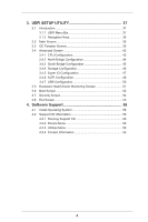
Contents 5 1.2 Specifications 6 1.3 Unique Features 9 1.4 Motherboard Layout 12 1.5 I/O Panel 13 2. Installation 14 Pre- 17 2.5 Dual Graphics Operation Guide 18 2.6 Dual Monitor and Surround Display Features 20 2.7 ASRock Smart Remote Installation Guide 23 2.8 Jumpers Setup 25 - ASRock A75M-DGS | User Manual - Page 4
Event Monitoring Screen 51 3.6 Boot Screen 52 3.7 Security Screen 54 3.8 Exit Screen 55 4. Software Support 56 4.1 Install Operating System 56 4.2 Support CD Information 56 4.2.1 Running Support CD 56 4.2.2 Drivers Menu 56 4.2.3 Utilities Menu 56 4.2.4 Contact Information 56 4 - ASRock A75M-DGS | User Manual - Page 5
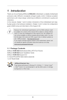
for specific information about the model you are using. www.asrock.com/support/index.asp 1.1 Package Contents ASRock A75M-DGS Motherboard (Micro ATX Form Factor) ASRock A75M-DGS Quick Installation Guide ASRock A75M-DGS Support CD 2 x Serial ATA (SATA) Data Cables (Optional) 1 x I/O Panel Shield - ASRock A75M-DGS | User Manual - Page 6
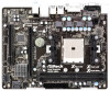
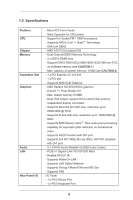
Chipset Memory Expansion Slot Graphics Audio LAN Rear Panel I/O - Micro ATX Form Factor - Solid Capacitor for CPU power - Support for Socket FM1 100W processors - Supports AMD's Cool 'n' QuietTM Technology - UMI-Link GEN2 - AMD A75 FCH (Hudson-D3) - Dual Channel DDR3 Memory Technology - 2 x DDR3 - ASRock A75M-DGS | User Manual - Page 7
with GUI support - Supports "Plug and Play" - ACPI 1.1 Compliance Wake Up Events - Supports jumperfree - SMBIOS 2.3.1 Support - CPU, DRAM, VDDP, SB Voltage Multi-adjustment Support CD - is required) * For detailed product information, please visit our website: http://www.asrock.com 7 - ASRock A75M-DGS | User Manual - Page 8
CPU you adopt. If you want to adopt DDR3 2400/1866/1600 memory module on this motherboard, please refer to the memory support list on our website for the compatible memory modules. ASRock website http://www.asrock.com 2. Due to the operating system limitation, the actual memory size may be less than - ASRock A75M-DGS | User Manual - Page 9
without sacrificing computing performance. In XFast RAM, it fully utilizes the memory space that cannot be used under Windows® OS 32-bit CPU. ASRock Instant Boot ASRock Instant Boot allows you to turn on your PC in just a few seconds, provides a much more efficient way to save energy, time, money - ASRock A75M-DGS | User Manual - Page 10
it makes your iPhone charge much quickly from your computer and up to 40% faster than before. ASRock APP Charger allows you to quickly charge many Apple devices simultaneously and even supports continuous charging when your PC enters into Standby mode (S1), Suspend to RAM (S3), hibernation mode (S4 - ASRock A75M-DGS | User Manual - Page 11
takes less than 1.5 seconds to logon to Windows® 8 from a cold boot. No more waiting! The speedy boot will completely change your user experience and behavior. ASRock Restart to UEFI Windows® 8 brings the ultimate boot up experience. The lightning boot up speed makes it hard to access the UEFI setup - ASRock A75M-DGS | User Manual - Page 12
) Fast USB X SOCKET FM1 DVI1 26 25 24 23 22 Top: LINE IN Center: FRONT Bottom: MIC IN USB 3.0 T: USB2 B: USB3 USB 3.0 T: USB4 B: USB5 USB 2.0 T: USB0 B: USB1 HD_AUDIO1 LAN AUDIO CODEC COM1 1 RJ-45 LAN 1 ErP/EuP Ready RoHS CMOS BATTERY 1 CLRCMOS1 A75M-DGS PCIE1 Super I/O DX11 32Mb - ASRock A75M-DGS | User Manual - Page 13
1.5 I/O Panel 1 11 10 9 1 PS/2 Mouse Port (Green) * 2 LAN RJ-45 Port 3 Line In (Light Blue) ** 4 Front Speaker (Lime) 5 Microphone (Pink) 6 USB 2.0 Ports (USB01) 2 3 4 5 8 7 6 7 USB 3.0 Ports (USB45) 8 USB 3.0 Ports (USB23) 9 DVI-D Port 10 D-Sub Port 11 PS/2 Keyboard Port (Purple) * There - ASRock A75M-DGS | User Manual - Page 14
the power is switched off or the power cord is detached from the power supply. Failure to do so may cause severe damage to the motherboard, peripherals, and/or components. 1. Unplug the power cord from the wall socket before touching any component. 2. To avoid damaging the - ASRock A75M-DGS | User Manual - Page 15
Lever Triangle 2.2 Installation of CPU Fan and Heatsink After you install the CPU into this motherboard, it is necessary to install a larger heatsink and cooling fan to dissipate heat. You For proper installation, please kindly refer to the instruction manuals of the CPU fan and the heatsink. 15 - ASRock A75M-DGS | User Manual - Page 16
2.3 Installation of Memory Modules (DIMM) This motherboard provides two 240-pin DDR3 (Double Data Rate 3) DIMM slots, and supports Dual Channel Memory Technology. For dual channel configuration, you always need to install two identical (the same brand, speed, size and chiptype) memory modules in - ASRock A75M-DGS | User Manual - Page 17
the expansion card and make necessary hardware settings for the card before you start the installation. Step 2. Remove the system unit cover (if your motherboard is already installed in a chassis). Step 3. Remove the bracket facing the slot that you intend to use. Keep the screws for later use. Step - ASRock A75M-DGS | User Manual - Page 18
2.5 AMD Dual Graphics Operation Guide This motherboard supports AMD Dual Graphics feature. AMD Dual Graphics ? An AMD Dual Graphics system includes an AMD Radeon HD 65XX/64XX graphics processor and a motherboard based on an AMD A75 FCH (Hudson-D3) integrated chipset, all operating in a Windows® - ASRock A75M-DGS | User Manual - Page 19
Step 7. You can also click "AMD VISION Engine Control Center" on your Windows® taskbar to enter AMD VISION Engine Control Center. AMD VISION Engine Control Center Step 8. In AMD VISION Engine Control Center, please choose "Performance". Click "AMD CrossFireTM". Step 9. Click "Enable CrossFireTM" and - ASRock A75M-DGS | User Manual - Page 20
easily enjoy the benefits of dual monitor feature without installing any add-on VGA card to this motherboard. This motherboard also provides independent display controllers for D-Sub and DVI-D to support dual VGA output so that D-Sub and DVI-D can drive same or different display contents. To enable - ASRock A75M-DGS | User Manual - Page 21
Surround Display Feature This motherboard supports surround display upgrade. With the internal VGA output support (D-Sub and DVI Auto], will disable D-Sub function when the add-on VGA card is inserted to this motherboard. 4. Install the onboard VGA driver and the add-on PCI Express VGA card driver - ASRock A75M-DGS | User Manual - Page 22
function is supported on this motherboard. To use HDCP function with this motherboard, you need to adopt the monitor that supports HDCP function as well. Therefore, you can enjoy the superior display quality with high-definition HDCP encryption contents. Please refer to below instruction for more - ASRock A75M-DGS | User Manual - Page 23
2.7 ASRock Smart Remote Installation Guide ASRock Smart Remote is only used for ASRock motherboard with CIR header. Please refer to below procedures for the quick installation and usage of ASRock Smart Remote. Step1. Find the CIR header located next to the USB 2.0 header on ASRock motherboard. - ASRock A75M-DGS | User Manual - Page 24
chassis on the market. 3. The Multi-Angle CIR Receiver does not support Hot-Plug function. Please install it before you boot the system. * ASRock Smart Remote is only supported by some of ASRock motherboards. Please refer to ASRock website for the motherboard support list: http://www.asrock.com 24 - ASRock A75M-DGS | User Manual - Page 25
, and then shut it down before you do the clear-CMOS ac- tion. Please be noted that the password, date, time, user default profile, 1394 GUID and MAC address will be cleared only if the CMOS battery is removed. 25 - ASRock A75M-DGS | User Manual - Page 26
the SATA data cable can be connected to the SATA3 hard disk or the SATA3 connector on this motherboard. Print Port Header (25-pin LPT1) (see p.12 No. 17) AFD# ERROR# PINIT# on the I/O panel, there are two USB 2.0 headers on this motherboard. Each USB 2.0 header can support two USB 2.0 ports. 26 - ASRock A75M-DGS | User Manual - Page 27
allows convenient connection and control of audio devices. 1. High Definition Audio supports Jack Sensing, but the panel wire on the chassis must support HDA to function correctly. Please follow the instruction in our manual and chassis manual to install your system. 2. If you use AC'97 audio - ASRock A75M-DGS | User Manual - Page 28
FAN_SPEED_CONTROL Please connect the CPU fan cable to the connector and match the black wire to the ground pin. Though this motherboard provides 4-Pin CPU fan (Quiet Fan) support, the 3-Pin CPU fan still can work successfully even without the fan speed control function. If you plan to connect - ASRock A75M-DGS | User Manual - Page 29
) (see p.12 No. 7) Please connect an ATX power supply to this connector. 1 13 Though this motherboard provides 24-pin ATX power connector, 12 24 it can still work if you adopt a traditional 20-pin Header (9-pin COM1) (see p.12 No.21) This COM1 header supports a serial port module. 29 - ASRock A75M-DGS | User Manual - Page 30
adopts AMD A75 FCH (Hudson-D3) chipset that supports Serial ATA3 (SATA3) hard disks and RAID (RAID 0, RAID 1 and RAID 10) functions. You may install SATA3 hard disks on this motherboard for internal storage devices. This section will guide you to install the SATA3 hard disks. STEP 1: Install - ASRock A75M-DGS | User Manual - Page 31
limitation, the SATA3 Hot Plug support information of our motherboard is indicated in the product spec on our website: www.asrock.com 2. Make sure your SATA3 HDD can support Hot Plug function from your dealer or HDD user manual. The SATA3 HDD, which cannot support Hot Plug function, will be damaged - ASRock A75M-DGS | User Manual - Page 32
data cable to end (White) to the power supply 1x4-pin the motherboard's SATAII / SATA3 cable. connector. SATA power cable 1x4-pin power of attention, before you process the Hot Unplug: Please do follow below instruction sequence to process the Hot Unplug, improper procedure will cause the SATA3 - ASRock A75M-DGS | User Manual - Page 33
Guide To install the drivers to your system, please insert the support CD to your optical drive first. Then, the drivers compatible to your system can be auto-detected and listed on the support floppy or a floppy disk.) A. Insert the ASRock Support CD into your optical drive to boot your system - ASRock A75M-DGS | User Manual - Page 34
guide in the Support CD for proper configuration. Please refer to the BIOS RAID installation guide part of the document in the following path in the Support CD: .. \ RAID Installation Guide STEP the optical drive to boot your system, and follow the instruction to install OS on your system. 34 - ASRock A75M-DGS | User Manual - Page 35
When you see "Where do you want to install Windows?" page, please insert the USB flash to your system, and click the "Load Driver" button to load the RAID drivers. After that, you can continue the OS installation. 2.15 Installing Windows® 8 / 8 64-bit / 7 / 7 64-bit / VistaTM / VistaTM 64-bit / XP - ASRock A75M-DGS | User Manual - Page 36
2.15.2 Installing Windows® 8 / 8 64-bit / 7 / 7 64-bit / VistaTM / VistaTM 64-bit Without RAID Functions If you want to install Windows® 8 / 8 64-bit / 7 / 7 64-bit / VistaTM / VistaTM 64-bit on your SATA3 HDDs without RAID functions, please follow below steps. Using SATA3 HDDs with NCQ and Hot - ASRock A75M-DGS | User Manual - Page 37
3. UEFI SETUP UTILITY 3.1 Introduction This section explains how to use the UEFI SETUP UTILITY to configure your system. The UEFI chip on the motherboard stores the UEFI SETUP UTILITY. You may run the UEFI SETUP UTILITY when you start up the computer. Please press or during the - ASRock A75M-DGS | User Manual - Page 38
3.1.2 Navigation Keys Please check the following table for the function description of each navigation key. Navigation Key(s) Function Description / Moves cursor left or right to select Screens / Moves cursor up or down to select items + / - To change option for the selected items - ASRock A75M-DGS | User Manual - Page 39
that overclocing may cause damage to your components and motherboard. It should be done at your own risk and item appears only when the processor you adopt supports this feature. Use this to select enable Auto] by default. If it is set to [Manual], you may adjust the value of Processor Frequency and - ASRock A75M-DGS | User Manual - Page 40
Timing Configuration DRAM Frequency If [Auto] is selected, the motherboard will detect the memory module(s) inserted and assigns appropriate frequency CAS# Latency (tCL) Use this item to change CAS# Latency (tCL) Auto/Manual setting. The default is [Auto]. RAS# to CAS# Delay (tRCD) Use this - ASRock A75M-DGS | User Manual - Page 41
setting. The default is [Auto]. Four Activate Window (tFAW) Use this item to change Four Activate Window (tFAW) Auto/Manual setting. The default is [Auto]. Voltage Control DRAM Voltage Use this to select DRAM Voltage. The default value is [Auto]. NB Voltage Use this to - ASRock A75M-DGS | User Manual - Page 42
Would you like to save current setting user defaults? In this option, you are allowed to load and save three user defaults according to your own requirements. 3.4 Advanced Screen In this section, you may set the configurations for the following items: CPU Configuration, Nouth Bridge - ASRock A75M-DGS | User Manual - Page 43
3.4.1 CPU Configuration Core C6 Mode Use this item to enable or disable Core C6 mode. The default value is [Enabled]. Cstate Pmin Mode Use this item to enable or disable Cstate Pmin mode. The default value is [Disabled]. Cool 'n' Quiet Use this item to enable or disable AMD's Cool 'n' QuietTM - ASRock A75M-DGS | User Manual - Page 44
disable the "Onboard HDMI HD Audio" feature. Dual Graphics This item appears only when you install AMD RADEON HD6670 / 6570 / 6450 graphics card on this motherboard. Use this to enable or disable Dual Graphics feature. If you enable this option, you can choose onboard VGA or PCIE card VGA at will - ASRock A75M-DGS | User Manual - Page 45
3.4.3 South Bridge Configuration Onboard HD Audio Select [Auto], [Enabled] or [Disabled] for the onboard HD Audio feature. If you select [Auto], the onboard HD Audio will be disabled when PCI Sound Card is plugged. Front Panel Select [Auto] or [Disabled] for the onboard HD Audio Front Panel. - ASRock A75M-DGS | User Manual - Page 46
3.4.4 Storage Configuration SATA Controller Use this item to enable or disable the "SATA Controller" feature. SATA Mode Use this item to adjust SATA Mode. The default value of this option is [AHCI Mode]. Configuration options: [AHCI Mode], [RAID Mode] and [IDE Mode]. Hard Disk S.M.A.R.T. Use this - ASRock A75M-DGS | User Manual - Page 47
3.4.5 Super IO Configuration Serial Port Use this item to enable or disable the onboard serial port. Serial Port Address Use this item to set the address for the onboard serial port. Configuration options: [3F8 / IRQ4] and [3E8 / IRQ4]. Infrared Port Use this item to enable or disable the - ASRock A75M-DGS | User Manual - Page 48
RAM Use this item to select whether to auto-detect or disable the Suspend-toRAM feature. Select [Auto] will enable this feature if the OS supports it. Check Ready Bit Use this item to enable or disable the feature Check Ready Bit. Restore on AC/Power Loss This allows you to - ASRock A75M-DGS | User Manual - Page 49
ACPI HPET table Use this item to enable or disable ACPI HPET Table. The default value is [Enabled]. Please set this option to [Enabled] if you plan to use this motherboard to submit Windows® certification. CSM Please disable CSM when you enable Fast Boot option. The default value is [Enabled]. 49 - ASRock A75M-DGS | User Manual - Page 50
use of USB 2.0 controller. USB 3.0 Controller Use this item to enable or disable the use of USB 3.0 controller. Legacy USB Support Use this option to select legacy support for USB devices. There are four confi guration options: [Enabled], [Auto], [Disabled] and [UEFI Setup Only]. The default value - ASRock A75M-DGS | User Manual - Page 51
the status of the hardware on your system, including the parameters of the CPU temperature, motherboard temperature, CPU fan speed, chassis fan speed, and the critical voltage. CPU Fan 1 1 speed. Confi guration options: [Full On], [Manual Mode] and [Automatic Mode]. The default is value [Full On]. 51 - ASRock A75M-DGS | User Manual - Page 52
using an USB flash drive. [Ultra Fast] - There are a few restrictions. 1. Only supports Windows® 8 UEFI operating system. 2. You will not be able to enter BIOS Setup 3. If you are using an external graphics card, the VBIOS must support UEFI GOP in order to boot. Setup Prompt Timeout This shows the - ASRock A75M-DGS | User Manual - Page 53
AddOn ROM Display Use this option to adjust AddOn ROM Display. If you enable the option "Full Screen Logo" but you want to see the AddOn ROM information when the system boots, please select [Enabled]. Configuration options: [Enabled] and [Disabled]. The default value is [Enabled]. Boot From - ASRock A75M-DGS | User Manual - Page 54
3.7 Security Screen In this section, you may set or change the supervisor/user password for the system. For the user password, you may also clear it. Secure Boot Use this to enable or disable Secure Boot. The default value is [Disabled]. 54 - ASRock A75M-DGS | User Manual - Page 55
3.8 Exit Screen Save Changes and Exit When you select this option, it will pop-out the following message, "Save configuration changes and exit setup?" Select [OK] to save the changes and exit the UEFI SETUP UTILITY. Discard Changes and Exit When you select this option, it will pop-out the following - ASRock A75M-DGS | User Manual - Page 56
applications software that the motherboard supports. Click on a specific item then follow the installation wizard to install it. 4.2.4 Contact Information If you need to contact ASRock or want to know more about ASRock, welcome to visit ASRock's website at http://www.asrock - ASRock A75M-DGS | User Manual - Page 57
Installing OS on a HDD Larger Than 2TB This motherboard is adopting UEFI BIOS that allows Windows® OS to be installed on a large size HDD (>2TB). Please follow below procedure to install the operating system. 1. - ASRock A75M-DGS | User Manual - Page 58
a HDD Larger Than 2TB in RAID Mode This motherboard is adopting UEFI BIOS that allows Windows® OS to UEFI Mode For GPT partition. Press to save the change and exit. 4. Press to enter Boot Manual. Choose UEFI : Built - in EFI Shell. 5. Key in drvcfg, for example you will see below: Drv[4E - ASRock A75M-DGS | User Manual - Page 59
7. And then key in drvcfg -s [Drv number] [Ctrl number] to enter Raid Utility. For example: key in drvcfg -s 4E B5. 8. Choose Logical Drive Main Menu to set up Raid Drive. 9. Choose Logical Drive Create Menu to create a Raid Drive. 10. Choose Usable Physical Drive List to select Raid HDD. 59 - ASRock A75M-DGS | User Manual - Page 60
. After set up Raid size, please click Start to Create. 14. Press to exit Utility. 15. During reboot, please press to enter Boot Manual. Choose UEFI: SCSI CD/DVD Drive. * This option only shows on Windows® 8 64-bit, 7 64-bit and VistaTM 64-bit OS. 60 - ASRock A75M-DGS | User Manual - Page 61
Windows® Installation Guide to install OS. If you install Windows® 8 64-bit / 7 64-bit / VistaTM 64-bit in a large hard disk (ex. Disk volume > 2TB), it may take more time to boot into Windows® or install driver/utilities. If you encounter this problem, you will need to following instructions to fix - ASRock A75M-DGS | User Manual - Page 62
B. Disable "Volume Shadow Copy" service. a. Type "computer management" in the Start Menu, then press "Enter". b. Go to "Services and Applications>Services"; Then double click "Volume Shadow Copy". c. Set "Startup type" to "Disable" then Click "OK". 62 - ASRock A75M-DGS | User Manual - Page 63
C. Reboot your system. D. After reboot, please start to install motherboard drivers and utilities. Windows® 8 64-bit / 7 64-bit: A. Please request the hotfix KB2505454 thru this link: http://support.microsoft.com/kb/2505454/ B. After installing Windows® 8 64-bit / 7 64-bit, install the hotfix
-
 1
1 -
 2
2 -
 3
3 -
 4
4 -
 5
5 -
 6
6 -
 7
7 -
8
-
9
-
10
-
11
-
12
-
13
-
14
-
15
-
16
-
17
-
18
-
19
-
20
-
21
-
22
-
23
-
24
-
25
-
26
-
27
-
28
-
29
-
30
-
31
-
32
-
33
-
34
-
35
-
36
-
37
-
38
-
39
-
40
-
41
-
42
-
43
-
44
-
45
-
46
-
47
-
48
-
49
-
50
-
51
-
52
-
53
-
54
-
55
-
56
-
57
-
58
-
59
-
60
-
61
-
62
-
63
 |
 |
1
A75M-DGS
User Manual
Version 1.0
Published November 2012
Copyright©2012 ASRock INC. All rights reserved.