ASRock A790GX/128M User Manual
ASRock A790GX/128M Manual
 |
View all ASRock A790GX/128M manuals
Add to My Manuals
Save this manual to your list of manuals |
ASRock A790GX/128M manual content summary:
- ASRock A790GX/128M | User Manual - Page 1
A790GX/128M User Manual Version 1.0 Published January 2009 Copyright©2009 ASRock INC. All rights reserved. 1 - ASRock A790GX/128M | User Manual - Page 2
any form or by any means, except duplication of documentation by the purchaser for backup purpose, without written consent of ASRock Inc. Products and corporate names appearing in this manual may or may not be registered trademarks or copyrights of their respective companies, and are used only for - ASRock A790GX/128M | User Manual - Page 3
Hardware Requirement for 1080p Blu-ray (BD) / HD-DVD Playback Support 10 1.4 1080p Blu-ray (BD) / HD-DVD Films Which Guide ....... 38 2.15 Driver Installation Guide 40 2.16 Installing Windows® XP / XP 64-bit / VistaTM / VistaTM 64-bit With RAID Functions 40 2.16.1 Installing Windows® XP / XP 64 - ASRock A790GX/128M | User Manual - Page 4
60 3.6 Boot Screen 61 3.6.1 Boot Settings Configuration 61 3.7 Security Screen 62 3.8 Exit Screen 63 4 . Software Support 64 4.1 Install Operating System 64 4.2 Support CD Information 64 4.2.1 Running Support CD 64 4.2.2 Drivers Menu 64 4.2.3 Utilities Menu 64 4.2.4 Contact Information - ASRock A790GX/128M | User Manual - Page 5
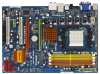
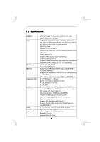
information about the model you are using. www.asrock.com/support/index.asp 1.1 Package Contents 1 x ASRock A790GX/128M Motherboard (ATX Form Factor: 12.0-in x 8.4-in, 30.5 cm x 21.3 cm) 1 x ASRock A790GX/128M Quick Installation Guide 2 x ASRock A790GX/128M Support CD 1 x Ultra ATA 66/100/133 IDE - ASRock A790GX/128M | User Manual - Page 6
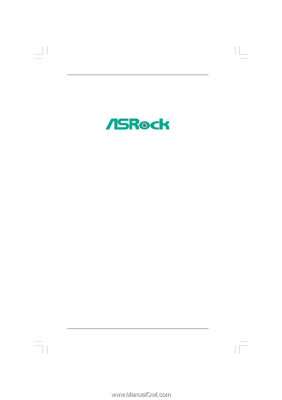
cm - Solid Capacitor for CPU power - Support for Socket AM2+ / AM2 processors: AMD PhenomTM FX / Phenom / Athlon 64 FX / Athlon 64 X2 Dual-Core / Athlon X2 Dual-Core / Athlon 64 / Sempron processor - AM3 CPU Ready - Supports CPU up to 140W - Supports AMD OverDriveTM with ACC feature (Advanced Clock - ASRock A790GX/128M | User Manual - Page 7
Play" - ACPI 1.1 Compliance Wake Up Events - Supports jumperfree - SMBIOS 2.3.1 Support - CPU, DRAM, NB Voltage Multi-adjustment - Supports Smart BIOS - Drivers, Utilities, AntiVirus Software (Trial Version), AMD OverDriveTM Utility, AMD Live! Explorer, AMD Fusion - ASRock OC Tuner (see CAUTION 10 - ASRock A790GX/128M | User Manual - Page 8
XP Media Center / XP 64-bit / VistaTM / VistaTM 64-bit compliant Certifications - FCC, guide of memory modules on page 17 for proper installation. 3. Whether 1066MHz memory speed is supported memory support list on our website for the compatible memory modules. ASRock website http://www.asrock.com - ASRock A790GX/128M | User Manual - Page 9
Setup Guide" on page 36 to adjust your SATAII hard disk drive to SATAII mode. You can also connect SATA hard disk to SATAII connector directly. 9. Power Management for USB 2.0 works fine under Microsoft® Windows® VistaTM 64-bit / VistaTM / XP 64-bit / XP SP1 or SP2. 10. It is a user-friendly ASRock - ASRock A790GX/128M | User Manual - Page 10
ray (BD) / HD-DVD Playback Support 1080p Blu-ray (BD) / HD-DVD playback support on this motherboard requires the proper 1080p Blu-ray (BD) / HD-DVD playback is only supported under Windows® VistaTM / VistaTM 64-bit OS. If you install Windows® XP / XP 64-bit OS, the function of 1080p Blu-ray (BD) - ASRock A790GX/128M | User Manual - Page 11
CPU AMD Sempron Dual Core 2100 VGA Onboard VGA with DVI-D port Memory Dual Channel DDR2 533, 1GB x 2 OS Windows® VistaTM or Windows® VistaTM 64 Playback Software CyberLink PowerDVD Ultra (Version 7.3 or above) DVD Player Pioneer BDR-101A / LG GBW-H10N (BD) HP HD100 (HD-DVD) 11 - ASRock A790GX/128M | User Manual - Page 12
6GHz DVI_CON1 VGA1 DDRII_3 (64 bit, 240-piFnSmBod8ul0e)0 DDRII_4 (64 bit, 240-pin module) DDRII_2 (64 bit, 240-pin module) DDRII_1 (64 bit, 240-piFnSmBod8ul0e)0 DDR2 1066 Dual Channel Super I/O AUDIO CODEC PCIE2 A790GX/128M PCI1 CrossFireX PCIE3 AMD SB750 Chipset RAID SATAII_5 SATAII_6 - ASRock A790GX/128M | User Manual - Page 13
1 . 6 I/O Panel 1 2 14 13 1 PS/2 Mouse Port (Green) 2 VGA/D-Sub Port * 3 LAN RJ-45 Port 4 Side Speaker (Gray) 5 Rear Speaker (Black) 6 Central / Bass (Orange) 7 Line In (Light Blue) 3 47 58 69 12 11 10 ** 8 Front Speaker (Lime) 9 Microphone (Pink) 10 USB 2.0 Ports (USB01) 11 USB 2.0 Ports ( - ASRock A790GX/128M | User Manual - Page 14
header. After restarting your computer, you will find "VIA HD Audio Deck" tool on your system. Please follow below instructions according to the OS you install. For Windows® XP / XP 64-bit OS: Please click "VIA HD Audio Deck" icon , and click "Speaker". Then you are allowed to select "2 Channel - ASRock A790GX/128M | User Manual - Page 15
2. Installation This is an ATX form factor (12.0-in x 8.4-in, 30.5 cm x 21.3 cm) motherboard. Before you install the motherboard, study the configuration of your chassis to ensure that the motherboard fits into it. Pre-installation Precautions Take note of the following precautions before you - ASRock A790GX/128M | User Manual - Page 16
each other. Then connect the CPU fan to the CPU FAN connector (CPU_FAN1, see Page 12, No. 5). For proper installation, please kindly refer to the instruction manuals of the CPU fan and the heatsink. 16 - ASRock A790GX/128M | User Manual - Page 17
2.3 Installation of Memory Modules (DIMM) This motherboard provides four 240-pin DDR2 (Double Data Rate 2) DIMM slots, and supports Dual Channel Memory Technology. For dual channel configuration, you always need to install identical (the same brand, speed, size and chip-type) DDR2 DIMM pair - ASRock A790GX/128M | User Manual - Page 18
Installing a DIMM Please make sure to disconnect power supply before adding or removing DIMMs or the system components. Step 1. Step 2. Unlock a DIMM slot by pressing the retaining clips outward. Align a DIMM on the slot such that the notch on the DIMM matches the break on the slot. notch break - ASRock A790GX/128M | User Manual - Page 19
x16 lane width graphics cards, or used to install PCI Express graphics cards to support CrossFireXTM function. PCIE2 (PCIE x16 slot; Orange) is used for PCI Express x1 and CrossFireXTM setup procedures, please refer to "CrossFireXTM Operation Guide" on page 23. Installing an expansion card Step 1. - ASRock A790GX/128M | User Manual - Page 20
D-Sub monitor cable to VGA/D-Sub port on the I/O panel. VGA/D-Sub port VGA/DVI-D port 2. If you have installed onboard VGA driver from our support CD to your system already, you can freely enjoy the benefits of dual monitor function after your system boots. If you haven't installed onboard VGA - ASRock A790GX/128M | User Manual - Page 21
surround display upgrade. With the internal VGA output support (DVI-D and D-Sub) and external add-on PCI is no need to install them again. 5. Set up a multi-monitor display. For Windows® XP / XP 64-bit OS: Right click the desktop, choose "Properties", and select the "Settings" tab so that you can - ASRock A790GX/128M | User Manual - Page 22
For Windows® VistaTM / VistaTM 64-bit OS: Right click the desktop, choose "Personalize", and the monitor that supports HDCP function as well. Therefore, you can enjoy the superior display quality with high-definition HDCP encryption contents. Please refer to below instruction for more details about - ASRock A790GX/128M | User Manual - Page 23
2.6 CrossFireXTM Operation Guide This motherboard supports CrossFireXTM feature. CrossFireXTM technology offers the most advantageous means image quality in any 3D application. Currently CrossFireXTM feature is supported with Windows® XP with Service Pack 2 and VistaTM OS. Please check AMD website - ASRock A790GX/128M | User Manual - Page 24
. For other CrossFireXTM cards that ATITM has released or will release in the future, please refer to ATIXTM graphics card manuals for detailed installation guide. Step 1. Install one Radeon graphics card to PCIE1 slot. For the proper installation procedures, please refer to section "Expansion Slots - ASRock A790GX/128M | User Manual - Page 25
Step 7. Step 8. Step 9. Install the required drivers to your system. For Windows® XP OS: A. ATITM recommends Windows® XP Service Pack 2 or higher to be installed (If you have Windows® XP Service Pack 2 or higher installed in your system, there is no need to download it again): http://www.microsoft - ASRock A790GX/128M | User Manual - Page 26
Step 10. Double-click "ATI Catalyst Control Center". Click "View", and select "Advanced View". Click "CrossFireTM", and then set the option "Enable CrossFireTM" to "Yes". View CrossFireTM Enable CrossFireTM Although you have selected the option "Enable CrossFireTM", CrossFireXTM function may not - ASRock A790GX/128M | User Manual - Page 27
. 7 ATITM Hybrid CrossFireXTM Operation Guide This motherboard supports ATITM Hybrid CrossFireXTM feature. ATITM Hybrid any VGA driver installed in your system. Step 5. Install the onboard VGA driver from our support CD to your system for both the onboard VGA and the discrete graphics card. Step 6. - ASRock A790GX/128M | User Manual - Page 28
Step 7. Double-click "ATI Catalyst Control Center". Click "View", click "CrossFireTM", and then select the option "Enable CrossFireTM". View CrossFireTM Enable CrossFireTM Step 8. Click "Yes" to continue. Step 9. Click "OK" to save your change. Step 10. Reboot your system. Then you can freely - ASRock A790GX/128M | User Manual - Page 29
2.8 Jumpers Setup The illustration shows how jumpers are setup. When the jumper cap is placed on pins, the jumper is "Short". If no jumper cap is placed on pins, the jumper is "Open". The illustration shows a 3-pin jumper whose pin1 and pin2 are "Short" when jumper cap is placed on these 2 pins. - ASRock A790GX/128M | User Manual - Page 30
80-conductor ATA 66/100/133 cable Note: Please refer to the instruction of your IDE device vendor for the details. Serial ATAII Connectors (SATAII_1 SATAII_5 SATAII_6 SATAII_1 SATAII_3 These six Serial ATAII (SATAII) connectors support SATAII or SATA hard disk for internal storage devices. The - ASRock A790GX/128M | User Manual - Page 31
allows convenient connection and control of audio devices. 1. High Definition Audio supports Jack Sensing, but the panel wire on the chassis must support HDA to function correctly. Please follow the instruction in our manual and chassis manual to install your system. 2. If you use AC'97 audio panel - ASRock A790GX/128M | User Manual - Page 32
the CPU fan cable to this connector and match the black wire to the ground pin. Though this motherboard provides 4-Pin CPU fan (Quiet Fan) support, the 3-Pin CPU fan still can work successfully even without the fan speed control function. If you plan to connect the 3-Pin CPU fan to - ASRock A790GX/128M | User Manual - Page 33
4 1 Serial port Header (9-pin COM1) (see p.12 No.29) RRXD1 DDTR#1 DDSR#1 CCTS#1 1 RRI#1 RRTS#1 GND TTXD1 DDCD#1 This COM1 header supports a serial port module. HDMI_SPDIF Header (3-pin HDMI_SPDIF1) (see p.12 No. 32) 1 GND +5V SPDIFOUT HDMI_SPDIF header, providing SPDIF audio output to HDMI - ASRock A790GX/128M | User Manual - Page 34
HDMI_SPDIF Cable (Optional) C B A Please connect the black end (A) of HDMI_SPDIF cable to the HDMI_SPDIF header on the motherboard. Then connect the white end (B or C) of HDMI_SPDIF cable to the HDMI_SPDIF connector of HDMI VGA card. A. black end +5V SPDIFOUT GND blue black B. white end (2-pin) - ASRock A790GX/128M | User Manual - Page 35
For the proper installation of HDMI VGA card, please refer to the installation guide on page 19. Step 2. Connect the black end (A) of HDMI_SPDIF cable to connector of PCI Express VGA card. Please refer to the VGA card user manual for connector usage in advance. Step 4. Step 5. Connect the HDMI - ASRock A790GX/128M | User Manual - Page 36
guide. Some default setting of SATAII hard disks may not be at SATAII mode, which operate with the best performance. In order to enable SATAII function, please follow the below instruction 's website for details: http://www.hitachigst.com/hdd/support/download.htm The above examples are just for your - ASRock A790GX/128M | User Manual - Page 37
/ SATAII hard disks on this motherboard for internal storage devices. This section will guide you to install the SATA / SATAII hard disks. STEP 1: Install the SATA / AHCI mode. AMD SB750 south bridge chipset provides hardware support for Advanced Host controller Interface (AHCI), a new programming - ASRock A790GX/128M | User Manual - Page 38
into system properly. The latest SATA / SATAII driver is available on our support website: www.asrock.com 4. Make sure to use the SATA power cable & data cable, which are from our motherboard package. 5. Please follow below instructions step by step to reduce the risk of HDD crash or data loss - ASRock A790GX/128M | User Manual - Page 39
the SATA / SATAII HDD. How to Hot Unplug a SATA / SATAII HDD: Points of attention, before you process the Hot Unplug: Please do follow below instruction sequence to process the Hot Unplug, improper procedure will cause the SATA / SATAII HDD damage and data loss. Step 1 Unplug SATA data cable from - ASRock A790GX/128M | User Manual - Page 40
your system. (There are two ASRock Support CD in the motherboard gift box pack, please choose the one for Windows® XP / XP 64-bit.) B. During POST at the Guide" to set RAID configuration. Before you start to configure RAID function, you need to check the RAID installation guide in the Support - ASRock A790GX/128M | User Manual - Page 41
disk into the optical drive to boot your system, and follow the instruction to install Windows® VistaTM / Windows® VistaTM 64-bit OS on your system. When you see "Where do you want to install Windows? " page, please insert the ASRock Support CD into your optical drive, and click the "Load Driver - ASRock A790GX/128M | User Manual - Page 42
first. Then, please set the RAID configuration by using the Windows RAID installation guide in the following path in the Support CD: .. \ RAID Installation Guide NOTE2. Currently, if you install Windows® VistaTM / Windows® VistaTM 64-bit on IDE HDDs and there are no SATA / SATAII device used, please - ASRock A790GX/128M | User Manual - Page 43
disk into the optical drive to boot your system, and follow the instruction to install Windows® VistaTM / Windows® VistaTM 64-bit OS on your system. When you see "Where do you want to install Windows? " page, please insert the ASRock Support CD into your optical drive, and click the "Load Driver - ASRock A790GX/128M | User Manual - Page 44
3. BIOS SETUP UTILITY 3.1 Introduction This section explains how to use the BIOS SETUP UTILITY to configure your system. The SPI Memory on the motherboard stores the BIOS SETUP UTILITY. You may run the BIOS SETUP UTILITY when you start up the computer. Please press during the Power-On-Self-Test - ASRock A790GX/128M | User Manual - Page 45
Main Smart Advanced H/W Monitor Boot Security Exit System Overview System Time System Date [17:00:09] [Thu 01/08/2008] BIOS Version : A790GX/128M P1.0 Processor Type : AMD Phenom(tm) 9350e Quad-Core Processor (64bit) Processor Speed : 2000MHz Microcode Update : 100F23/1000083 L1 Cache Size - ASRock A790GX/128M | User Manual - Page 46
3.3 Smart Screen In the Smart screen, you can load the BIOS setup according to your requirements. BIOS SETUP UTILITY Main Smart Advanced H/W Monitor Boot Security Exit Smart Settings Save Changes and Exit Load BIOS Defaults Load Performance Setup Default (IDE/SATA) Load Performance Setup AHCI Mode - ASRock A790GX/128M | User Manual - Page 47
If AUTO, multiplier and voltage will be left at the rated frequency/voltage. If Manual, multiplier and voltage will be set based on User Selection in Setup. +F1 CPU. If you set this option to [Enabled], you will enable ASRock AM2 Boost function, which will improve the memory performance. The default - ASRock A790GX/128M | User Manual - Page 48
processors support the Halt State (C1). The C1 state is supported through the native processor instructions HLT and MWAIT and requires no hardware support from item is set to [Auto] by default. If it is set to [Manual], you may adjust the value of Processor Frequency and Processor Voltage. However, - ASRock A790GX/128M | User Manual - Page 49
of this item. Processor Voltage This option appears only when you adopt AM2 CPU. This item will show when "Multiplier/Voltage Change" is set to [Manual]; otherwise, it will be hidden. The range of the value depends on the CPU you adopt on this motherboard. However, for safety and system stability - ASRock A790GX/128M | User Manual - Page 50
Flexibility Option The default value of this option is [Disabled]. It will allow better tolerance for memory compatibility when it is set to [Enabled]. Memory Controller Mode This option appears only when you adopt Phenom CPU. It allows you to adjust the memory controller mode. Configuration options - ASRock A790GX/128M | User Manual - Page 51
TWRWR This option appears only when you adopt AM2 CPU. Use this to adjust TWRWR values. Configuration options: [Auto], [1CLK], [2CLK] and [3CLK]. The default value is [Auto]. TRDRD This option appears only when you adopt AM2 CPU. Use this to adjust TRWTTD values. Configuration options: [Auto], [2CLK - ASRock A790GX/128M | User Manual - Page 52
3.4.2 Chipset Configuration BIOS SETUP UTILITY Advanced Chipset Settings Onboard HD Audio Front Panel OnBoard Lan Primary Graphics Adapter [Auto] [Auto] [Enabled] [PCI] Internal Graphics Mode Share Memory SidePort Clock Speed Onboard HDMI HD Audio Onboard GPU Clock Override Surround View - ASRock A790GX/128M | User Manual - Page 53
Onboard HDMI HD Audio This allows you to enable or disable the onboard HDMI HD Audio in AMD 790GX. Onboard GPU Clock Override This allows you to enable or disable the Onboard GPU Clock Override feature. Onboard GPU Clock This option only appears when you enable "Onboard GPU Clock Override". The - ASRock A790GX/128M | User Manual - Page 54
RAM Use this item to select whether to auto-detect or disable the Suspend-toRAM feature. Select [Auto] will enable this feature if the OS supports it. If you set this item to [Disabled], the function "Repost Video on STR Resume" will be hidden. Repost Video on STR Resume This feature - ASRock A790GX/128M | User Manual - Page 55
We will use the "IDE1 Master" as the example in the following instruction, which can be applied to the configurations of "IDE1 Slave" as well :Hard Disk :MAXTOR 6L080J4 :80.0 GB :Supported :16Sectors :4 :MultiWord DMA-2 :Ultra DMA-6 :Supported Type LBA/Large Mode Block (Multi-Sector Transfer) - ASRock A790GX/128M | User Manual - Page 56
TYPE Use this item to configure the type of the IDE device that you specify. Configuration options: [Not Installed], [Auto], [CD/DVD], and [ARMD]. [Not Installed]: Select [Not Installed] to disable the use of IDE device. [Auto]: Select [Auto] to automatically detect the hard disk drive. After - ASRock A790GX/128M | User Manual - Page 57
3.4.5PCIPnP Configuration BIOS SETUP UTILITY Advanced Advanced PCI / PnP Settings PCI Latency Timer PCI IDE BusMaster [32] [Enabled] Value in units of PCI clocks for PCI device latency timer register. +F1 F9 F10 ESC Select Screen Select Item Change Option General Help Load Defaults Save and - ASRock A790GX/128M | User Manual - Page 58
3.4.6Floppy Configuration In this section, you may configure the type of your floppy drive. BIOS SETUP UTILITY Advanced Floppy Configuration Floppy A [1.44 MB 312"] Select the type of floppy drive connected to the system. +F1 F9 F10 ESC Select Screen Select Item Change Option General Help Load - ASRock A790GX/128M | User Manual - Page 59
default value is [BIOS Setup Only]. Please refer to below descriptions for the details of these four options: [Enabled] - Enables support for legacy USB. [Auto] - Enables legacy support if USB devices are connected. [Disabled] - USB devices are not allowed to use under legacy OS and BIOS setup when - ASRock A790GX/128M | User Manual - Page 60
3.5 Hardware Health Event Monitoring Screen In this section, it allows you to monitor the status of the hardware on your system, including the parameters of the CPU temperature, motherboard temperature, CPU fan speed, chassis fan speed, and the critical voltage. BIOS SETUP UTILITY Main Smart - ASRock A790GX/128M | User Manual - Page 61
3.6 Boot Screen In this section, it will display the available devices on your system for you to configure the boot settings and the boot priority. BIOS SETUP UTILITY Main Smart Advanced H/W Monitor Boot Security Exit Boot Settings Boot Settings Configuration Configure Settings during System - ASRock A790GX/128M | User Manual - Page 62
logo in POST screen. This option only appears when you enable the option "Full Screen Logo". Configuration options: [Auto], [PCIE2.0 Revolution], [Scenery] and [ASRock]. The default value is [Auto]. Currently, the option [Auto] is set to Aircraft. Boot From Onboard LAN Use this item to enable or - ASRock A790GX/128M | User Manual - Page 63
3.8 Exit Screen BIOS SETUP UTILITY Main Smart Advanced H/W Monitor Boot Security Exit Exit Options Save Changes and Exit Discard Changes and Exit Discard Changes Would you like to save current setting user defaults ? Save 1st User Defaults Load 1st User Defaults Save 2nd User Defaults Load 2nd - ASRock A790GX/128M | User Manual - Page 64
applications software that the motherboard supports. Click on a specific item then follow the installation wizard to install it. 4.2.4 Contact Information If you need to contact ASRock or want to know more about ASRock, welcome to visit ASRock's website at http://www.asrock.com; or you may contact
-
 1
1 -
 2
2 -
 3
3 -
 4
4 -
 5
5 -
 6
6 -
 7
7 -
8
-
9
-
10
-
11
-
12
-
13
-
14
-
15
-
16
-
17
-
18
-
19
-
20
-
21
-
22
-
23
-
24
-
25
-
26
-
27
-
28
-
29
-
30
-
31
-
32
-
33
-
34
-
35
-
36
-
37
-
38
-
39
-
40
-
41
-
42
-
43
-
44
-
45
-
46
-
47
-
48
-
49
-
50
-
51
-
52
-
53
-
54
-
55
-
56
-
57
-
58
-
59
-
60
-
61
-
62
-
63
-
64
 |
 |
1
A790GX/128M
User Manual
Version 1.0
Published January 2009
Copyright©2009 ASRock INC. All rights reserved.