ASRock AD2550B-ITX User Manual
ASRock AD2550B-ITX Manual
 |
View all ASRock AD2550B-ITX manuals
Add to My Manuals
Save this manual to your list of manuals |
ASRock AD2550B-ITX manual content summary:
- ASRock AD2550B-ITX | User Manual - Page 1
AD2550B-ITX User Manual Version 1.0 Published April 2012 Copyright©2012 ASRock INC. All rights reserved. 1 - ASRock AD2550B-ITX | User Manual - Page 2
constructed as a commitment by ASRock. ASRock assumes no responsibility for any errors or omissions that may appear in this manual. With respect to the contents of this manual, ASRock USA ONLY The Lithium battery adopted on this motherboard contains Perchlorate, a toxic substance controlled in - ASRock AD2550B-ITX | User Manual - Page 3
Installation 21 2.9 Hot Plug and Hot Swap Functions for SATA / SATA2 HDDs 21 2.10 SATA / SATA2 HDD Hot Plug Feature and Operation Guide 22 2.11 Driver Installation Guide 24 2.12 Installing Windows® 7 on SATA / SATAII HDDs ........ 24 3 UEFI SETUP UTILITY 25 3.1 Introduction 25 3.1.1 UEFI Menu - ASRock AD2550B-ITX | User Manual - Page 4
4 Software Support 39 4.1 Install Operating System 39 4.2 Support CD Information 39 4.2.1 Running Support CD 39 4.2.2 Drivers Menu 39 4.2.3 Utilities Menu 39 4.2.4 Contact Information 39 4 - ASRock AD2550B-ITX | User Manual - Page 5
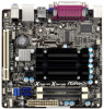
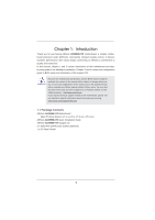
about the model you are using. www.asrock.com/support/index.asp 1.1 Package Contents ASRock AD2550B-ITX Motherboard (Mini-ITX Form Factor: 6.7-in x 6.7-in, 17.0 cm x 17.0 cm) ASRock AD2550B-ITX Quick Installation Guide ASRock AD2550B-ITX Support CD 2 x Serial ATA (SATA) Data Cables (Optional - ASRock AD2550B-ITX | User Manual - Page 6
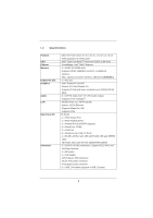
Slot Graphics Audio LAN Rear Panel I/O Connector - Mini-ITX Form Factor: 6.7-in x 6.7-in, 17.0 cm x 17.0 cm - Solid Capacitor for CPU power - Intel® Dual-Core AtomTM Processor D2550 (1.86 GHz) - Southbridge: Intel® NM10 Express - 2 x DDR3 SO-DIMM slots - Supports DDR3 1066/800 non-ECC, un-buffered - ASRock AD2550B-ITX | User Manual - Page 7
, +5V, +3.3V, CPU Vcore OS - Microsoft® Windows® 7 32-bit compliant Certifications - FCC, CE, WHQL - ErP/EuP Ready (ErP/EuP ready power supply is required) (see CAUTION 11) * For detailed product information, please visit our website: http://www.asrock.com WARNING Please realize that there is - ASRock AD2550B-ITX | User Manual - Page 8
your computer and up to 40% faster than before. ASRock APP Charger allows you to quickly charge many Apple devices simultaneously and even supports continuous charging when your PC enters into Standby mode (S1), Suspend to RAM (S3), hibernation mode (S4) or power off (S5). With APP Charger driver - ASRock AD2550B-ITX | User Manual - Page 9
power loss occurs during the BIOS update process, ASRock Crashless BIOS will automatically finish the BIOS update procedure after regaining power. Please note that BIOS files need to be placed in the root directory of your USB disk. Only USB2.0 ports support this feature. 9. Although this motherboard - ASRock AD2550B-ITX | User Manual - Page 10
) DDR3_A1 (64 bit, 204-FpiSnBm8o0d0ule) PARALLEL PORT COM1 Fast USB VGA1 Fa X st LAN X 18 Top: Line In Center: Line Out Bottom: Mic In USB 2.0 T: USB2 B: USB3 RoHS USB 2.0 T: USB0 B: USB1 Top: RJ-45 AUDIO CODEC LAN PHY CMOS Battery 16Mb BIOS 1 HD_AUDIO1 AD2550B-ITX PCI1 DX10 - ASRock AD2550B-ITX | User Manual - Page 11
) 6 Microphone (Pink) 7 USB 2.0 Ports (USB01) 8 USB 2.0 Ports (USB23) 9 VGA Port 10 COM Port 11 PS/2 Keyboard Port (Purple) * There are two LED next to the LAN After restarting your computer, you will find "VIA HD Audio Deck" tool on your system. Please follow below instructions according to the - ASRock AD2550B-ITX | User Manual - Page 12
This is a Mini-ITX form factor (6.7" x 6.7", 17.0 x 17.0 cm) motherboard. Before you install the motherboard, study the configuration of your chassis to ensure that the motherboard fits into it. Make sure to unplug the power cord before installing or removing the motherboard. Failure to do - ASRock AD2550B-ITX | User Manual - Page 13
DDR or DDR2 memory module into DDR3 slot; otherwise, this motherboard and SO-DIMM may be damaged. 2. Please install the memory module from DDR3_A2 slot for the first priority. Installing a SO-DIMM Please make sure to disconnect power supply before adding or removing SO-DIMMs or the system components - ASRock AD2550B-ITX | User Manual - Page 14
is 1 PCI slot on this motherboard. PCI slot: The PCI slot is used to install expansion card that has the 32-bit PCI interface. Installing an expansion card Step 1. Before installing the expansion card, please make sure that the power supply is switched off or the power cord is unplugged. Please read - ASRock AD2550B-ITX | User Manual - Page 15
find this option, please shut down your system and install Multi-Angle CIR Receiver to the other front USB port then try again. Step5. Enter Windows. Execute ASRock support CD and install CIR Driver. (It is listed at the bottom of - ASRock AD2550B-ITX | User Manual - Page 16
chassis on the market. 3. The Multi-Angle CIR Receiver does not support Hot-Plug function. Please install it before you boot the system. * ASRock Smart Remote is only supported by some of ASRock motherboards. Please refer to ASRock website for the motherboard support list: http://www.asrock.com 16 - ASRock AD2550B-ITX | User Manual - Page 17
on these 2 pins. Jumper Clear CMOS (CLRCMOS1, 2-pin jumper) (see p.10 No. 11) Setting 2-pin jumper Description Note: CLRCMOS1 allows you to clear parameters to default setup, please turn off the computer and unplug the power cord from the power supply. After waiting for 15 seconds, use a jumper - ASRock AD2550B-ITX | User Manual - Page 18
the default USB 2.0 ports on the I/O panel, there are two USB 2.0 headers on this motherboard. Each USB 2.0 header can support two USB 2.0 ports. Consumer Infrared Module Header (4-pin CIR1) (see p.10 No. 10) 1 GND IRTX IRRX ATX+5VSB This header can be used to connect the remote controller - ASRock AD2550B-ITX | User Manual - Page 19
supports Jack Sensing, but the panel wire on the chassis must support HDA to function correctly. Please follow the instruction in our manual and chassis manual restart the computer if the computer freezes and fails to perform a normal restart. PLED (System Power LED): Connect to the power status - ASRock AD2550B-ITX | User Manual - Page 20
pin. Please connect an ATX power supply to this connector. 1 13 Though this motherboard provides 24-pin ATX power connector, 12 24 it can still work if you adopt a traditional 20-pin ATX power supply. To use the 20-pin ATX power supply, please plug your power supply along with Pin 1 and Pin - ASRock AD2550B-ITX | User Manual - Page 21
(SATAII) Hard Disks Installation This motherboard adopts Intel® NM10 Express chipset that supports Serial ATA (SATA) / Serial ATAII (SATAII) hard disks. You may install SATA / SATAII hard disks on this motherboard for internal storage devices. This section will guide you to install the SATA / SATAII - ASRock AD2550B-ITX | User Manual - Page 22
is installed into system properly. The latest SATA / SATAII driver is available on our support website: www.asrock.com 4. Make sure to use the SATA power cable & data cable, which are from our motherboard package. 5. Please follow below instructions step by step to reduce the risk of HDD crash or - ASRock AD2550B-ITX | User Manual - Page 23
instruction sequence to process the Hot Plug, improper procedure will cause the SATA / SATAII HDD damage and data loss. Step 1 Please connect SATA power cable 1x4-pin end Step 2 Connect SATA data cable to (White) to the power supply 1x4-pin cable. the motherboard's SATAII connector. SATA power - ASRock AD2550B-ITX | User Manual - Page 24
compatible to your system can be auto-detected and listed on the support CD driver page. Please follow the order from up to bottom side to install those required drivers. Therefore, the drivers you install can work properly. 2.12 Installing Windows® 7 on SATA / SATAII HDDs If you want to install - ASRock AD2550B-ITX | User Manual - Page 25
motherboard stores the UEFI SETUP UTILITY. You may run the UEFI SETUP UTILITY when you start up the computer. Please press or during the Power-On-Self-Test back on. Because the UEFI software is constantly being updated, the following UEFI setup screens and descriptions are for reference - ASRock AD2550B-ITX | User Manual - Page 26
3.1.2 Navigation Keys Please check the following table for the function description of each navigation key. Navigation Key(s) Function Description / Moves cursor left or right to select Screens / Moves cursor up or down to select items + / - To change option for the selected items - ASRock AD2550B-ITX | User Manual - Page 27
to malfunction. Instant Flash Instant Flash is a UEFI flash utility embedded in Flash ROM. This convenient UEFI update tool allows you to update system UEFI without entering operating systems first like MS-DOS or Windows®. Just launch this tool and save the new UEFI file to your USB flash drive, floppy - ASRock AD2550B-ITX | User Manual - Page 28
enable this feature, it requires a computer system with an Intel processor that supports Hyper-Threading technology and an operating system that includes optimization for this technology, such as Microsoft® Windows® 7. Set to [Enabled] if using Microsoft® Windows® 7. No-Excute Memory Protection No - ASRock AD2550B-ITX | User Manual - Page 29
to use this motherboard to submit Windows® certification. Restore on AC/Power Loss This allows you to set the power state after an unexpected AC/power loss. If [Power Off] is selected, the AC/power remains off when the power recovers. If [Power On] is selected, the AC/power resumes and the system - ASRock AD2550B-ITX | User Manual - Page 30
this to select SATA2 mode. Configuration options: [IDE Mode], [AHCI Mode] and [Disabled]. The default value is [IDE Mode]. AHCI (Advanced Host Controller Interface) supports NCQ and other new features that will improve SATA disk performance but IDE mode does not have these advantages. 30 - ASRock AD2550B-ITX | User Manual - Page 31
Port Address Use this item to set the address for the onboard parallel port. Configuration options: [Auto], [IO=378h; IRQ=5; DMA=3], [IO=378h; IRQ=5, 6, 7, 9, 10, 11, 12; DMA=1, 3] and [IO=278h; IRQ - ASRock AD2550B-ITX | User Manual - Page 32
Suspend-toRAM feature. Select [Auto] will enable this feature if the OS supports it. Deep S5 Mobile platforms support Deep S5 in DC only and desktop platforms support Deep S5 in AC only. The default value is [Auto]. PS/2 Keyboard Power On Use this item to enable or disable PS/2 keyboard to turn on - ASRock AD2550B-ITX | User Manual - Page 33
to below descriptions for the details of these four options: [Enabled] - Enables support for legacy USB. [Auto] - Enables legacy support if USB devices are connected. [Disabled] - USB devices are not allowed to Only] - USB devices are allowed to use only under UEFI setup and Windows / Linux OS. 33 - ASRock AD2550B-ITX | User Manual - Page 34
3.3.7 Voltage Configuration DRAM Voltage Use this to select DRAM Voltage. The default value is [Auto]. +1.05V Voltage Use this to select +1.05V Voltage. The default value is [Auto]. +1.5V Voltage Use this to select +1.5V Voltage. The default value is [Auto]. 34 - ASRock AD2550B-ITX | User Manual - Page 35
Monitoring Screen In this section, it allows you to monitor the status of the hardware on your system, including the parameters of the CPU temperature, motherboard temperature, CPU fan speed, chassis fan speed, and the critical voltage. CPU Fan Setting This allows you to set the CPU fan speed. Con - ASRock AD2550B-ITX | User Manual - Page 36
3.5 Boot Screen In this section, it will display the available devices on your system for you to configure the boot settings and the boot priority. Setup Prompt Timeout This shows the number of seconds to wait for setup activation key. 65535(0XFFFF) means indefinite waiting. Bootup Num-Lock If this - ASRock AD2550B-ITX | User Manual - Page 37
3.6 Security Screen In this section, you may set or change the supervisor/user password for the system. For the user password, you may also clear it. 37 - ASRock AD2550B-ITX | User Manual - Page 38
3.7 Exit Screen Save Changes and Exit When you select this option, it will pop-out the following message, "Save configuration changes and exit setup?" Select [OK] to save the changes and exit the UEFI SETUP UTILITY. Discard Changes and Exit When you select this option, it will pop-out the following - ASRock AD2550B-ITX | User Manual - Page 39
with the motherboard contains necessary drivers and useful utilities that enhance the motherboard features. 4.2.1 Running The Support CD To begin using the support CD, insert the CD into your CD-ROM drive. The CD automatically displays the Main Menu if "AUTORUN" is enabled in your computer. If the
-
 1
1 -
 2
2 -
 3
3 -
 4
4 -
 5
5 -
 6
6 -
 7
7 -
8
-
9
-
10
-
11
-
12
-
13
-
14
-
15
-
16
-
17
-
18
-
19
-
20
-
21
-
22
-
23
-
24
-
25
-
26
-
27
-
28
-
29
-
30
-
31
-
32
-
33
-
34
-
35
-
36
-
37
-
38
-
39
 |
 |

1
AD2550B-ITX
User Manual
Version 1.0
Published April 2012
Copyright©2012 ASRock INC. All rights reserved.