ASRock AD2700B-ITX User Manual
ASRock AD2700B-ITX Manual
 |
View all ASRock AD2700B-ITX manuals
Add to My Manuals
Save this manual to your list of manuals |
ASRock AD2700B-ITX manual content summary:
- ASRock AD2700B-ITX | User Manual - Page 1
AD2700B-ITX / AD2500B-ITX User Manual Version 1.0 Published October 2011 Copyright©2011 ASRock INC. All rights reserved. 1 - ASRock AD2700B-ITX | User Manual - Page 2
purchaser for backup purpose, without written consent of ASRock Inc. Products and corporate names appearing in this manual may or may not be registered trademarks or copyrights , USA ONLY The Lithium battery adopted on this motherboard contains Perchlorate, a toxic substance controlled in Perchlorate - ASRock AD2700B-ITX | User Manual - Page 3
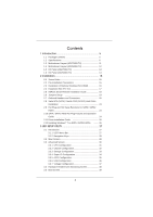
Motherboard Layout (AD2500B-ITX 12 1.5 I/O Panel (AD2700B-ITX 13 1.6 I/O Panel (AD2500B-ITX 14 2 Installation 15 2.1 Screw Holes 15 2.2 Pre-installation Precautions 15 2.3 Installation of Memory Modules (SO-DIMM 16 2.4 Expansion Slot (PCI Slot 17 2.5 ASRock Smart Remote Installation Guide - ASRock AD2700B-ITX | User Manual - Page 4
3.6 Security Screen 40 3.7 Exit Screen 41 4 Software Support 42 4.1 Install Operating System 42 4.2 Support CD Information 42 4.2.1 Running Support CD 42 4.2.2 Drivers Menu 42 4.2.3 Utilities Menu 42 4.2.4 Contact Information 42 4 - ASRock AD2700B-ITX | User Manual - Page 5
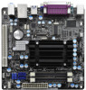
you are using. www.asrock.com/support/index.asp 1.1 Package Contents ASRock AD2700B-ITX / AD2500B-ITX Motherboard (Mini-ITX Form Factor: 6.7-in x 6.7-in, 17.0 cm x 17.0 cm) ASRock AD2700B-ITX / AD2500B-ITX Quick Installation Guide ASRock AD2700B-ITX / AD2500B-ITX Support CD 2 x Serial ATA (SATA - ASRock AD2700B-ITX | User Manual - Page 6
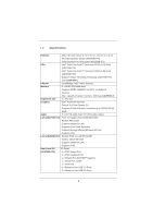
for CPU power (AD2500B-ITX) CPU - Intel® Dual-Core AtomTM Processor D2700 (2.13 GHz) (AD2700B-ITX) - Intel® Dual-Core AtomTM Processor D2500 (1.86 GHz) (AD2500B-ITX) - Supports Hyper-Threading Technology (AD2700B-ITX) (see CAUTION 1) Chipset - Southbridge: Intel® NM10 Express Memory - ASRock AD2700B-ITX | User Manual - Page 7
24 pin ATX power connector - Front panel audio connector - 2 x USB 2.0 headers (support 4 USB 2.0 ports) - 16Mb AMI BIOS - AMI UEFI Legal BIOS with GUI support - Supports "Plug and Play" - ACPI 1.1 Compliance Wake Up Events - Supports jumperfree - SMBIOS 2.3.1 Support - Drivers, Utilities, AntiVirus - ASRock AD2700B-ITX | User Manual - Page 8
, +5V, +3.3V, CPU Vcore OS - Microsoft® Windows® 7 32-bit compliant Certifications - FCC, CE, WHQL - ErP/EuP Ready (ErP/EuP ready power supply is required) (see CAUTION 10) * For detailed product information, please visit our website: http://www.asrock.com WARNING Please realize that there is - ASRock AD2700B-ITX | User Manual - Page 9
40% faster than before. ASRock APP Charger allows you to quickly charge many Apple devices simultaneously and even supports continuous charging when your PC enters into Standby mode (S1), Suspend to RAM (S3), hibernation mode (S4) or power off (S5). With APP Charger driver installed, you can easily - ASRock AD2700B-ITX | User Manual - Page 10
to define the power consumption for the completed system. According to EuP, the total AC power of the completed system should be under 1.00W in off mode condition. To meet EuP standards, an EuP ready motherboard and an EuP ready power supply are required. According to Intel's suggestion, the EuP - ASRock AD2700B-ITX | User Manual - Page 11
Motherboard Layout (AD2700B-ITX) PS2 Mouse PS2 Keyboard 1 2 3 17.0cm (6.7 in) CPU_FAN1 ErP/EuP Ready CHA_FAN1 4 Super IO 17.0cm (6.7 in) DDR3_A2 (64 bit, 204-FpiSnBm8o0d0ule) DDR3_A1 (64 bit , DDR3_A2, Black) 5 ATX Power Connector (ATXPWR1) 6 SATA2 Connector Intel NM10 Express Chip 11 - ASRock AD2700B-ITX | User Manual - Page 12
Motherboard Layout (AD2500B-ITX) PS2 Mouse PS2 Keyboard 1 2 3 17.0cm (6.7 in) CPU_FAN1 ErP/EuP Ready CHA_FAN1 4 Super IO 17.0cm (6.7 in) DDR3_A2 (64 bit, 204-FpiSnBm8o0d0ule) DDR3_A1 (64 bit , DDR3_A2, Black) 5 ATX Power Connector (ATXPWR1) 6 SATA2 Connector Intel NM10 Express Chip 12 - ASRock AD2700B-ITX | User Manual - Page 13
1.5 I/O Panel (AD2700B-ITX) 1 2 11 10 9 1 PS/2 Mouse Port (Green) 2 Parallel Port * 3 LAN RJ-45 Port 4 Line In (Light Blue) 5 , you will find "VIA HD Audio Deck" tool on your system. Please follow below instructions according to the OS you install. Please click "VIA HD Audio Deck" icon , and - ASRock AD2700B-ITX | User Manual - Page 14
1.6 I/O Panel (AD2500B-ITX) 1 PS/2 Mouse Port (Green) 2 Parallel Port * 3 LAN RJ-45 Port 4 Line In (Light Blue) 5 computer, you will find "VIA HD Audio Deck" tool on your system. Please follow below instructions according to the OS you install. Please click "VIA HD Audio Deck" icon , and click - ASRock AD2700B-ITX | User Manual - Page 15
This is a Mini-ITX form factor (6.7" x 6.7", 17.0 x 17.0 cm) motherboard. Before you install the motherboard, study the configuration of your chassis to ensure that the motherboard fits into it. Make sure to unplug the power cord before installing or removing the motherboard. Failure to do - ASRock AD2700B-ITX | User Manual - Page 16
2.3 Installation of Memory Modules (SO-DIMM) AD2700B-ITX / AD2500B-ITX motherboard provides two 240-pin DDR3 (Double Data Rate 3) SO-DIMM slots. 1. It is not allowed to install a DDR or DDR2 memory module into DDR3 slot; otherwise, this motherboard and SO-DIMM may be damaged. 2. Please install the - ASRock AD2700B-ITX | User Manual - Page 17
is 1 PCI slot on this motherboard. PCI slot: The PCI slot is used to install expansion card that has the 32-bit PCI interface. Installing an expansion card Step 1. Before installing the expansion card, please make sure that the power supply is switched off or the power cord is unplugged. Please read - ASRock AD2700B-ITX | User Manual - Page 18
chassis on the market. 3. The Multi-Angle CIR Receiver does not support Hot-Plug function. Please install it before you boot the system. * ASRock Smart Remote is only supported by some of ASRock motherboards. Please refer to ASRock website for the motherboard support list: http://www.asrock.com 18 - ASRock AD2700B-ITX | User Manual - Page 19
password, date, time, and system setup parameters. To clear and reset the system parameters to default setup, please turn off the computer and unplug the power cord from the power supply. After waiting for 15 seconds, use a jumper cap to short 2 pins on CLRCMOS1 for 5 seconds. 19 - ASRock AD2700B-ITX | User Manual - Page 20
pin USB6_7) (see p.11 or 12 No. 7) Besides the default USB 2.0 ports on the I/O panel, there are two USB 2.0 headers on this motherboard. Each USB 2.0 header can support two USB 2.0 ports. Consumer Infrared Module Header (4-pin CIR1) (see p.11 or 12 No. 10) 1 GND IRTX IRRX ATX+5VSB This header - ASRock AD2700B-ITX | User Manual - Page 21
Audio supports Jack Sensing, but the panel wire on the chassis must support HDA to function correctly. Please follow the instruction in our manual and chassis manual The LED is off when the system is in S3/S4 sleep state or powered off (S5). HDLED (Hard Drive Activity LED): Connect to the hard drive - ASRock AD2700B-ITX | User Manual - Page 22
the ground pin. Please connect the CPU fan cable to the connector and match the black wire to the ground pin. Please connect an ATX power supply to this connector. 1 13 Though this motherboard provides 24-pin ATX power connector, 12 24 it can still work if you adopt a traditional 20-pin ATX - ASRock AD2700B-ITX | User Manual - Page 23
motherboard adopts Intel® NM10 Express chipset that supports Serial ATA (SATA) / Serial ATAII (SATAII) hard disks. You may install SATA / SATAII hard disks on this motherboard for internal storage devices. This section will guide HDDs while the system is still power-on and in working condition. - ASRock AD2700B-ITX | User Manual - Page 24
is installed into system properly. The latest SATA / SATAII driver is available on our support website: www.asrock.com 4. Make sure to use the SATA power cable & data cable, which are from our motherboard package. 5. Please follow below instructions step by step to reduce the risk of HDD crash or - ASRock AD2700B-ITX | User Manual - Page 25
instruction sequence to process the Hot Plug, improper procedure will cause the SATA / SATAII HDD damage and data loss. Step 1 Please connect SATA power cable 1x4-pin end Step 2 Connect SATA data cable to (White) to the power supply 1x4-pin cable. the motherboard's SATAII connector. SATA power - ASRock AD2700B-ITX | User Manual - Page 26
compatible to your system can be auto-detected and listed on the support CD driver page. Please follow the order from up to bottom side to install those required drivers. Therefore, the drivers you install can work properly. 2.12 Installing Windows® 7 on SATA / SATAII HDDs If you want to install - ASRock AD2700B-ITX | User Manual - Page 27
UEFI SETUP UTILITY to configure your system. The UEFI chip on the motherboard stores the UEFI SETUP UTILITY. You may run the UEFI SETUP UTILITY when > or during the Power-On-Self-Test (POST) to enter the UEFI SETUP UTILITY, otherwise, POST will continue with its test routines. If you wish to - ASRock AD2700B-ITX | User Manual - Page 28
Screen or exit the current screen 3.2 Main Screen When you enter the UEFI SETUP UTILITY, the Main screen will appear and display the system overview. AD2700B-ITX 28 - ASRock AD2700B-ITX | User Manual - Page 29
AD2500B-ITX 29 - ASRock AD2700B-ITX | User Manual - Page 30
utility embedded in Flash ROM. This convenient UEFI update tool allows you to update system UEFI without entering operating systems first like MS-DOS or Windows®. Just launch this tool and save the new UEFI file to your USB flash drive, floppy disk or hard drive, then you can update your - ASRock AD2700B-ITX | User Manual - Page 31
feature, it requires a computer system with an Intel processor that supports Hyper-Threading technology and an operating system that includes optimization for this technology, such as Microsoft® Windows® 7. Set to [Enabled] if using Microsoft® Windows® 7. No-Excute Memory Protection No-Execution (NX - ASRock AD2700B-ITX | User Manual - Page 32
to use this motherboard to submit Windows® certification. Restore on AC/Power Loss This allows you to set the power state after an unexpected AC/power loss. If [Power Off] is selected, the AC/power remains off when the power recovers. If [Power On] is selected, the AC/power resumes and the system - ASRock AD2700B-ITX | User Manual - Page 33
this to select SATA2 mode. Configuration options: [IDE Mode], [AHCI Mode] and [Disabled]. The default value is [IDE Mode]. AHCI (Advanced Host Controller Interface) supports NCQ and other new features that will improve SATA disk performance but IDE mode does not have these advantages. 33 - ASRock AD2700B-ITX | User Manual - Page 34
3.3.4 Super IO Configuration COM1 Port Use this item to enable or disable the onboard serial port. COM1 Port Address Use this item to set the address for the onboard serial port. Configuration options: [3F8 / IRQ4] and [3E8 / IRQ4]. IR1 Port Use this item to enable or disable the onboard infrared - ASRock AD2700B-ITX | User Manual - Page 35
Suspend-toRAM feature. Select [Auto] will enable this feature if the OS supports it. Deep S5 Mobile platforms support Deep S5 in DC only and desktop platforms support Deep S5 in AC only. The default value is [Auto]. PS/2 Keyboard Power On Use this item to enable or disable PS/2 keyboard to turn on - ASRock AD2700B-ITX | User Manual - Page 36
issue, it is recommended to select [Disabled] to enter OS. [UEFI Setup Only] - USB devices are allowed to use only under UEFI setup and Windows / Linux OS. Legacy USB 3.0 Support Use this option to enable or disable legacy support for USB 3.0 devices. The default value is [Disabled]. 36 - ASRock AD2700B-ITX | User Manual - Page 37
3.3.7 Voltage Configuration DRAM Voltage Use this to select DRAM Voltage. The default value is [Auto]. +1.05V Voltage Use this to select +1.05V Voltage. The default value is [Auto]. +1.5V Voltage Use this to select +1.5V Voltage. The default value is [Auto]. 37 - ASRock AD2700B-ITX | User Manual - Page 38
Monitoring Screen In this section, it allows you to monitor the status of the hardware on your system, including the parameters of the CPU temperature, motherboard temperature, CPU fan speed, chassis fan speed, and the critical voltage. CPU Fan Setting This allows you to set the CPU fan speed. Con - ASRock AD2700B-ITX | User Manual - Page 39
3.5 Boot Screen In this section, it will display the available devices on your system for you to configure the boot settings and the boot priority. Setup Prompt Timeout This shows the number of seconds to wait for setup activation key. 65535(0XFFFF) means indefinite waiting. Bootup Num-Lock If this - ASRock AD2700B-ITX | User Manual - Page 40
3.6 Security Screen In this section, you may set or change the supervisor/user password for the system. For the user password, you may also clear it. 40 - ASRock AD2700B-ITX | User Manual - Page 41
3.7 Exit Screen Save Changes and Exit When you select this option, it will pop-out the following message, "Save configuration changes and exit setup?" Select [OK] to save the changes and exit the UEFI SETUP UTILITY. Discard Changes and Exit When you select this option, it will pop-out the following - ASRock AD2700B-ITX | User Manual - Page 42
install the necessary drivers to activate the devices. 4.2.3 Utilities Menu The Utilities Menu shows the applications software that the motherboard supports. Click on a specific item then follow the installation wizard to install it. 4.2.4 Contact Information If you need to contact ASRock or want to
-
 1
1 -
 2
2 -
 3
3 -
 4
4 -
 5
5 -
 6
6 -
 7
7 -
8
-
9
-
10
-
11
-
12
-
13
-
14
-
15
-
16
-
17
-
18
-
19
-
20
-
21
-
22
-
23
-
24
-
25
-
26
-
27
-
28
-
29
-
30
-
31
-
32
-
33
-
34
-
35
-
36
-
37
-
38
-
39
-
40
-
41
-
42
 |
 |

1
AD2700B-ITX /
AD2500B-ITX
User Manual
Version 1.0
Published October 2011
Copyright©2011 ASRock INC. All rights reserved.