ASRock AD410PV Quick Installation Guide - Page 12
English, 5 Jumpers Setup
 |
View all ASRock AD410PV manuals
Add to My Manuals
Save this manual to your list of manuals |
Page 12 highlights
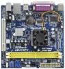
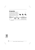
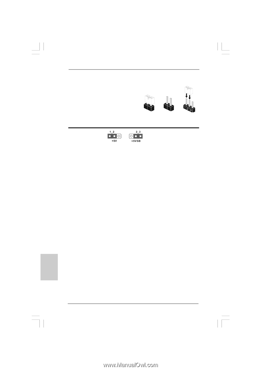
2.5 Jumpers Setup The illustration shows how jumpers are setup. When the jumper cap is placed on pins, the jumper is "Short". If no jumper cap is placed on pins, the jumper is "Open". The illustration shows a 3-pin jumper whose pin1 and pin2 are "Short" when jumper cap is Short Open placed on these 2 pins. Jumper Setting Description PS2_USB_PWR1 Short pin2, pin3 to enable (see p.2 No. 1) +5VSB (standby) for PS/2 or USB wake up events. Note: To select +5VSB, it requires 2 Amp and higher standby current provided by power supply. English 12 ASRock AD510PV / AD410PV Motherboard
-
 1
1 -
2
-
3
-
4
-
5
-
6
-
 7
7 -
 8
8 -
 9
9 -
 10
10 -
 11
11 -
 12
12 -
 13
13 -
 14
14 -
 15
15 -
 16
16 -
 17
17 -
18
-
19
-
20
-
21
-
22
-
23
-
24
-
25
-
26
-
27
-
28
-
29
-
30
-
31
-
32
-
33
-
34
-
35
-
36
-
37
-
38
-
39
-
40
-
41
-
42
-
43
-
44
-
45
-
46
-
47
-
48
-
49
-
50
-
51
-
52
-
53
-
54
-
55
-
56
-
57
-
58
-
59
-
60
-
61
-
62
-
63
-
64
-
65
-
66
-
67
-
68
-
69
-
70
-
71
-
72
-
73
-
74
-
75
-
76
-
77
-
78
-
79
-
80
-
81
-
82
-
83
-
84
-
85
-
86
-
87
-
88
-
89
-
90
-
91
-
92
-
93
-
94
-
95
-
96
-
97
-
98
-
99
-
100
-
101
-
102
-
103
-
104
-
105
-
106
-
107
-
108
-
109
-
110
-
111
-
112
-
113
-
114
-
115
-
116
-
117
-
118
-
119
-
120
-
121
 |
 |
12
12
12
12
12
ASRock
AD510PV / AD410PV
Motherboard
English
English
English
English
English
2.5 Jumpers Setup
2.5 Jumpers Setup
2.5 Jumpers Setup
2.5 Jumpers Setup
2.5 Jumpers Setup
The illustration shows how jumpers are
setup. When the jumper cap is placed on
pins, the jumper is “Short”. If no jumper cap
is placed on pins, the jumper is “Open”. The
illustration shows a 3-pin jumper whose pin1
and pin2 are “Short” when jumper cap is
placed on these 2 pins.
Jumper
Setting
Description
PS2_USB_PWR1
Short pin2, pin3 to enable
(see p.2
No. 1)
+5VSB (standby) for PS/2
or USB wake up events.
Note:
To select +5VSB, it requires 2 Amp and higher standby current provided by
power supply.
Short
Open