ASRock ALiveNF6G-GLAN User Manual - Page 22
con nect HDMI Digital TV
 |
View all ASRock ALiveNF6G-GLAN manuals
Add to My Manuals
Save this manual to your list of manuals |
Page 22 highlights
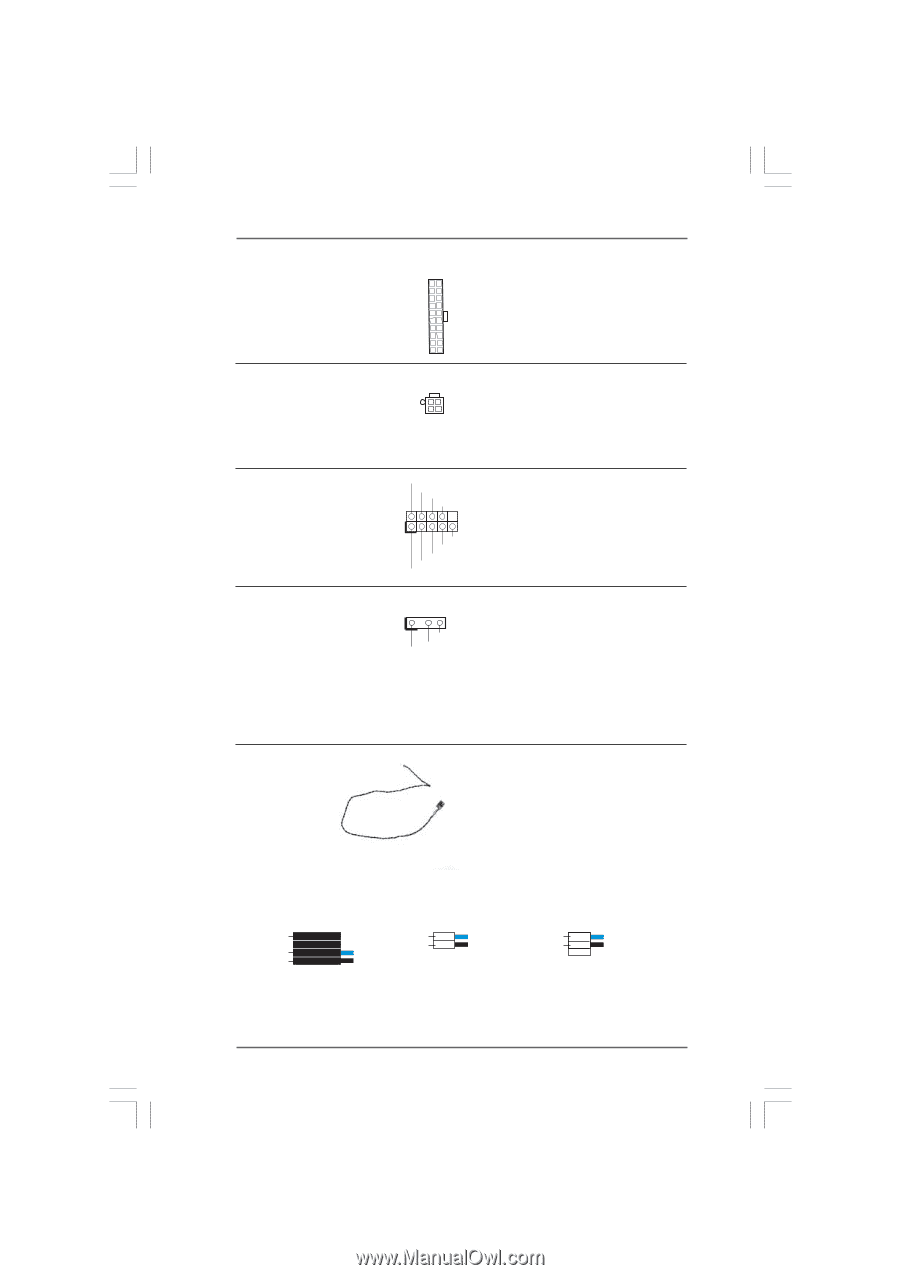
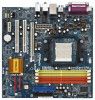
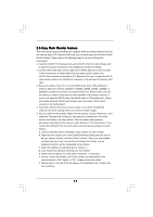
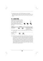
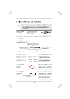
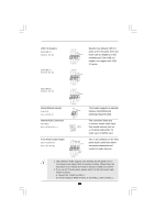
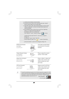
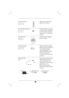
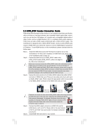
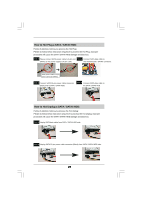
ATX Power Connector (20-pin ATXPWR1) (see p.10 No. 30) Please connect an ATX power supply to this connector. ATX 12V Power Connector (4-pin ATX12V1) (see p.10 No. 2) Serial port Header (9-pin COM1) (see p.10 No.31) HDMI_SPDIF Header (3-pin HDMI_SPDIF1) (see p.10 No. 25) RRXD1 DDTR#1 DDSR#1 CCTS#1 1 RRI#1 RRTS#1 GND TTXD1 DDCD#1 1 GND SPDIFOUT +5V HDMI_SPDIF Cable (Optional) C B A Please note that it is necessary to connect a power supply with ATX 12V plug to this connector. Failing to do so will cause power up failure. This COM1 header supports a serial port module. HDMI_SPDIF header, providing SPDIF audio output to HDMI VGA card, allows the system to connect HDMI Digital TV/ projector/LCD devices. Please connect the HDMI_SPDIF connector of HDMI VGA card to this header. Please connect the black end (A) of HDMI_SPDIF cable to the HDMI_SPDIF header on the motherboard. Then connect the white end (B or C) of HDMI_SPDIF cable to the HDMI_SPDIF connector of HDMI VGA card. A. black end +5V SPDIFOUT GND B. white end (2-pin) C. white end (3-pin) blue black SPDIFOUT GND blue black SPDIFOUT GND blue black 22
-
 1
1 -
2
-
3
-
4
-
5
-
6
-
7
-
8
-
9
-
10
-
11
-
12
-
13
-
14
-
15
-
16
-
 17
17 -
 18
18 -
 19
19 -
 20
20 -
 21
21 -
 22
22 -
 23
23 -
 24
24 -
 25
25 -
 26
26 -
 27
27 -
28
-
29
-
30
-
31
-
32
-
33
-
34
-
35
-
36
-
37
-
38
-
39
-
40
-
41
-
42
-
43
-
44
-
45
-
46
-
47
-
48
-
49
 |
 |