ASRock ConRoeXFire-eSATA2 User Manual - Page 25
These four Serial ATA II
 |
View all ASRock ConRoeXFire-eSATA2 manuals
Add to My Manuals
Save this manual to your list of manuals |
Page 25 highlights
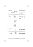
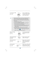
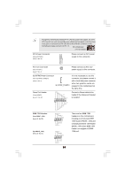
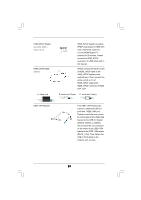
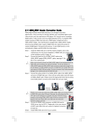
FDD connector (33-pin FLOPPY1) (see p.11 No. 26) Pin1 FLOPPY1 the red-striped side to Pin1 Note: Make sure the red-striped side of the cable is plugged into Pin1 side of the connector. Primary IDE connector (Blue) (39-pin IDE1, see p.11 No. 10) PIN1 IDE1 connect the blue end connect the black end to the motherboard to the IDE devices 80-conductor ATA 66/100 cable Note: Please refer to the instruction of your IDE device vendor for the details. Serial ATA II Connectors These four Serial ATA II (SATAII_BLUE (PORT0): (SATAII) connectors support see p.11, No. 16) SATAII_RED SATAII_ORANGE SATA data cables for internal (SATAII_BLACK (PORT1): (PORT2) (PORT3) storage devices. The current see p.11, No. 15) SATA II interface allows up to (SATAII_RED (PORT2): see p.11, No. 13) SATAII_BLUE SATAII_BLACK (PORT0) (PORT1) 3.0 Gb/s data transfer rate. (SATAII_ORANGE (PORT3): see p.11, No. 14) SATAII_RED (PORT2) and SATAII_ORANGE (PORT3) connectors can be used for internal storage devices or be connected to eSATAII_BOTTOM and eSATAII_TOP connectors with corresponding color to support eSATAII devices. Please read "eSATAII Interface Introduction" on page 31 for details about eSATAII and eSATAII installation procedures. eSATA II Connectors (eSATAII_TOP: see p.11, No. 37) (eSATAII_BOTTOM: see p.11, No. 38) eSATAII_TOP eSATAII_BOTTOM These two eSATA II connectors support SATA data cables for external SATAII function. The current eSATA II interface allows up to 3.0 Gb/s data transfer rate. Serial ATA (SATA) Data Cable (Optional) Either end of the SATA data cable can be connected to the SATA / SATAII hard disk or the SATAII connector on the motherboard. You can also use the SATA data cable to connect SATAII connectors and eSATAII connectors with corresponding color. 25
-
 1
1 -
2
-
3
-
4
-
5
-
6
-
7
-
8
-
9
-
10
-
11
-
12
-
13
-
14
-
15
-
16
-
17
-
18
-
19
-
 20
20 -
 21
21 -
 22
22 -
 23
23 -
 24
24 -
 25
25 -
 26
26 -
 27
27 -
 28
28 -
 29
29 -
 30
30 -
31
-
32
-
33
-
34
-
35
-
36
-
37
-
38
-
39
-
40
-
41
-
42
-
43
-
44
-
45
-
46
-
47
-
48
-
49
-
50
-
51
-
52
-
53
-
54
-
55
-
56
-
57
-
58
-
59
 |
 |
