ASRock E350M1/USB3 Quick Installation Guide - Page 17
English, 7 Onboard Headers and Connectors
 |
View all ASRock E350M1/USB3 manuals
Add to My Manuals
Save this manual to your list of manuals |
Page 17 highlights
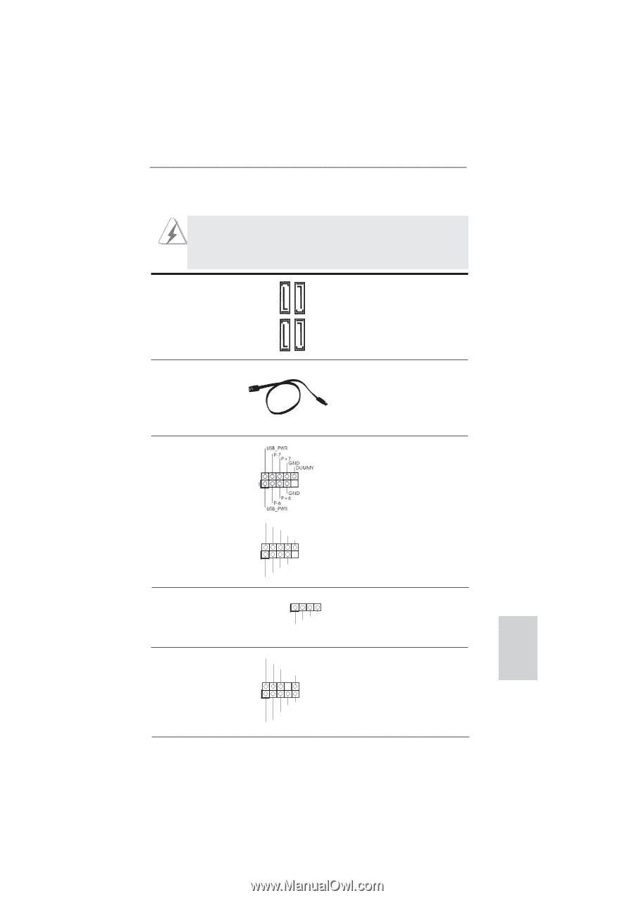
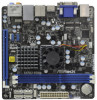
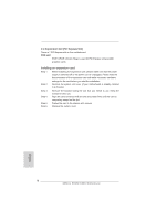
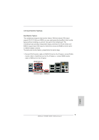
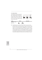
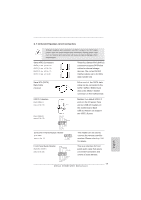
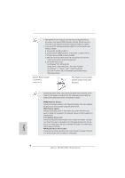
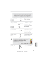
2.7 Onboard Headers and Connectors Onboard headers and connectors are NOT jumpers. Do NOT place jumper caps over these headers and connectors. Placing jumper caps over the headers and connectors will cause permanent damage of the motherboard! Serial ATA3 Connectors (SATA3_1: see p.2, No. 12) (SATA3_2: see p.2, No. 10) (SATA3_3: see p.2, No. 11) (SATA3_4: see p.2, No. 9) These four Serial ATA3 (SATA3) connectors support SATA data cables for internal storage devices. The current SATA3 interface allows up to 6.0 Gb/s data transfer rate. SATA3_1 SATA3_2 SATA3_3 SATA3_4 Serial ATA (SATA) Data Cable (Optional) Either end of the SATA data cable can be connected to the SATA / SATAII / SATA3 hard disk or the SATAII / SATA3 connector on this motherboard. USB 2.0 Headers (9-pin USB6_7) (see p.2 No. 19) (9-pin USB8_9) (see p.2 No. 18) USB_PWR P-9 P+9 GND DUMMY 1 GND P+8 P-8 USB_PWR Consumer Infrared Module Header (4-pin CIR1) (see p.2 No. 17) 1 GND IRTX IRRX ATX+5VSB Besides four default USB 2.0 ports on the I/O panel, there are two USB 2.0 headers on this motherboard. Each USB 2.0 header can support two USB 2.0 ports. This header can be used to connect the remote controller receiver. Please refer to p. 144 for details. Front Panel Audio Header (9-pin HD_AUDIO1) (see p.2 No. 20) GND PRESENCE# MIC_RET OUT_RET This is an interface for front panel audio cable that allows convenient connection and 1 control of audio devices. OUT2_L J_SENSE OUT2_R MIC2_R MIC2_L 17 ASRock E350M1/USB3 Motherboard English
-
 1
1 -
2
-
3
-
4
-
5
-
6
-
7
-
8
-
9
-
10
-
11
-
 12
12 -
 13
13 -
 14
14 -
 15
15 -
 16
16 -
 17
17 -
 18
18 -
 19
19 -
 20
20 -
 21
21 -
 22
22 -
23
-
24
-
25
-
26
-
27
-
28
-
29
-
30
-
31
-
32
-
33
-
34
-
35
-
36
-
37
-
38
-
39
-
40
-
41
-
42
-
43
-
44
-
45
-
46
-
47
-
48
-
49
-
50
-
51
-
52
-
53
-
54
-
55
-
56
-
57
-
58
-
59
-
60
-
61
-
62
-
63
-
64
-
65
-
66
-
67
-
68
-
69
-
70
-
71
-
72
-
73
-
74
-
75
-
76
-
77
-
78
-
79
-
80
-
81
-
82
-
83
-
84
-
85
-
86
-
87
-
88
-
89
-
90
-
91
-
92
-
93
-
94
-
95
-
96
-
97
-
98
-
99
-
100
-
101
-
102
-
103
-
104
-
105
-
106
-
107
-
108
-
109
-
110
-
111
-
112
-
113
-
114
-
115
-
116
-
117
-
118
-
119
-
120
-
121
-
122
-
123
-
124
-
125
-
126
-
127
-
128
-
129
-
130
-
131
-
132
-
133
-
134
-
135
-
136
-
137
-
138
-
139
-
140
-
141
-
142
-
143
-
144
 |
 |