ASRock H55 Pro User Manual
ASRock H55 Pro Manual
 |
View all ASRock H55 Pro manuals
Add to My Manuals
Save this manual to your list of manuals |
ASRock H55 Pro manual content summary:
- ASRock H55 Pro | User Manual - Page 1
H55 Pro User Manual Version 1.0 Published December 2009 Copyright©2009 ASRock INC. All rights reserved. 1 - ASRock H55 Pro | User Manual - Page 2
purchaser for backup purpose, without written consent of ASRock Inc. Products and corporate names appearing in this manual may or may not be registered trademarks or copyrights USA ONLY The Lithium battery adopted on this motherboard contains Perchlorate, a toxic substance controlled in Perchlorate - ASRock H55 Pro | User Manual - Page 3
6 1.3 Two CrossFireXTM Graphics Card Support List 11 1.4 Motherboard Layout 12 1.5 I/O Panel 13 HDDs 38 2.17 SATA / SATAII HDD Hot Plug Feature and Operation Guide 39 2.18 Driver Installation Guide 41 2.19 Installing Windows® 7 / 7 64-bit / VistaTM 42 2.20 Untied Overclocking Technology 43 3 - ASRock H55 Pro | User Manual - Page 4
BIOS Menu Bar 44 3.1.2 Navigation Keys 45 3.2 Main Screen 45 3.3 OC Tweaker Screen 46 3.4 Advanced Screen 49 3.4.1 CPU Configuration 50 3.4.2 Chipset 62 4 Software Support 63 4.1 Install Operating System 63 4.2 Support CD Information 63 4.2.1 Running Support CD 63 4.2.2 Drivers Menu 63 - ASRock H55 Pro | User Manual - Page 5
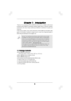
guide to BIOS setup and information of the Support CD. Because the motherboard specifications and the BIOS software might be updated, the content of this manual will be subject to change without notice. In case any modifications of this manual occur, the updated version will be available on ASRock - ASRock H55 Pro | User Manual - Page 6
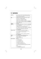
and Pentium® G6950 Processors in LGA1156 Package - Advanced V8 + 2 Power Phase Design - Supports Intel® Turbo Boost Technology - Supports Hyper-Threading Technology (see CAUTION 1) - Supports Untied Overclocking Technology (see CAUTION 2) - Supports EM64T CPU - Intel® H55 - Dual Channel DDR3 Memory - ASRock H55 Pro | User Manual - Page 7
PCH PLL Voltage Multi-adjustment - Supports I. O. T. (Intelligent Overclocking Technology) - Drivers, Utilities, AntiVirus Software (Trial Version), ASRock Software Suite (CyberLink DVD Suite and Creative Sound Blaster X-Fi MB) (OEM and Trial Version) - ASRock OC Tuner (see CAUTION 10) - Intelligent - ASRock H55 Pro | User Manual - Page 8
product information, please visit our website: http://www.asrock.com WARNING Please realize that there is a certain risk involved with overclocking, including adjusting the setting in the BIOS, applying Untied Overclocking Technology, or using the thirdparty overclocking tools. Overclocking - ASRock H55 Pro | User Manual - Page 9
operation procedures of Intelligent Energy Saver. ASRock website: http://www.asrock.com/feature/IES/index.html 12. ASRock Instant Flash is a BIOS flash utility embedded in Flash ROM. This convenient BIOS update tool allows you to update system BIOS without entering operating systems first like MS - ASRock H55 Pro | User Manual - Page 10
types, Socket LGA 775 and LGA 1156. Please be noticed that not all the 775 CPU Fan can be used. 17. EuP, stands for Energy Using Product, . To meet EuP standard, an EuP ready motherboard and an EuP ready power supply are required. According to Intel's suggestion, the EuP ready power supply must - ASRock H55 Pro | User Manual - Page 11
Catalyst 9.1 * The graphics cards with * mark are supported under Windows® VistaTM / VistaTM 64-bit only. * For the latest updates of the supported PCI Express VGA card list for CrossFireXTM Mode, please visit our website for details. ASRock website: http://www.asrock.com/support/index.htm 11 - ASRock H55 Pro | User Manual - Page 12
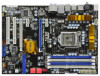
H55 Pro EuP Ready PCI Express 2.0 PCIE2 36 35 34 33 Super I/O PCIE3 PCIE4 AUDIO CODEC RoHS HD_AUDIO1 CD1 COM1 1 1 1 HDMI_SPDIF1 PCI1 PCI2 FLOPPY1 32 31 30 29 Intel H55 IDE1 JMicron JMB363 SPEAKER1 1 CI1 1 VIA VT6308S 1 CLRCMOS1 16Mb BIOS 3 1156-Pin CPU Socket 4 Intel H55 Chipset - ASRock H55 Pro | User Manual - Page 13
the speaker's plug into "Front Speaker Jack". See the table below for connection details in accordance with the type of speaker you use. TABLE for Audio Output Connection Audio Output Channels Front Speaker Rear Speaker Central / Bass Side Speaker (No. 10) (No. 7) (No. 8) (No - ASRock H55 Pro | User Manual - Page 14
To enable Multi-Streaming function, you need to connect a front panel audio cable to the front panel audio header. After restarting your computer, you will find "VIA HD Audio Deck" tool on your system. Please follow below instructions according to the OS you install. For Windows® XP / XP 64-bit - ASRock H55 Pro | User Manual - Page 15
Precautions Take note of the following precautions before you install motherboard components or change any motherboard settings. 1. Unplug the power cord from the wall socket before touching any component. 2. To avoid damaging the motherboard components due to static electricity, NEVER place your - ASRock H55 Pro | User Manual - Page 16
the installation of Intel 1156-Pin CPU, please follow the steps below. Load Plate Load Lever Contact Array Socket Body 1156-Pin Socket Overview Before you insert the 1156-Pin CPU into the socket, please check if cap. 2. This cap must be placed if returning the motherboard for after service. 16 - ASRock H55 Pro | User Manual - Page 17
Heat Sink) up. Locate Pin1 and the two orientation key notches. orientation key notch alignment key Pin1 Pin1 orientation key notch 1156-Pin CPU alignment key 1156-Pin Socket For proper inserting, please ensure to match the two orientation key notches of the CPU with the two alignment keys of - ASRock H55 Pro | User Manual - Page 18
2.4 Installation of CPU Fan and Heatsink This motherboard is equipped with 1156-Pin socket that supports Intel 1156-Pin CPU. Please adopt the type of heatsink and cooling fan compliant with Intel 1156-Pin CPU to dissipate heat. Before you installed the heatsink, you need to spray thermal interface - ASRock H55 Pro | User Manual - Page 19
2.5 Installation of Memory Modules (DIMM) This motherboard provides four 240-pin DDR3 (Double Data Rate 3) DIMM slots, and supports Dual Channel Memory Technology. For dual channel configuration, you always need to install identical (the same brand, speed, size and chiptype) DDR3 DIMM pair in - ASRock H55 Pro | User Manual - Page 20
matches the break on the slot. notch break notch break The DIMM only fits in one correct orientation. It will cause permanent damage to the motherboard and the DIMM if you force the DIMM into the slot at incorrect orientation. Step 3. Firmly insert the DIMM into the slot until the retaining - ASRock H55 Pro | User Manual - Page 21
lane width graphics cards, or used to install PCI Express graphics cards to support CrossFireXTM function. PCIE4 (PCIE x16 slot; White) is used for PCI the installation. Step 2. Remove the system unit cover (if your motherboard is already installed in a chassis). Step 3. Remove the bracket facing - ASRock H55 Pro | User Manual - Page 22
supported with Windows® XP with Service Pack 2 / VistaTM / 7 OS. Quad CrossFireXTM feature are supported with Windows® VistaTM / 7 OS only. Please check AMD website for ATITM CrossFireXTM driver updates refer to ATITM graphics card manuals for detailed installation guide. Step 1. Insert one Radeon - ASRock H55 Pro | User Manual - Page 23
Bridge Interconnects on the top of Radeon graphics cards. (CrossFire Bridge is provided with the graphics card you purchase, not bundled with this motherboard. Please refer to your graphics card vendor for details.) CrossFire Bridge or Step 2. Connect the DVI monitor cable to the DVI connector - ASRock H55 Pro | User Manual - Page 24
utility to uninstall any previously installed Catalyst drivers prior to installation. Please check AMD website for ATITM driver updates. Step 3. Step 4. Step 5. Install the required drivers to your system. For Windows® XP OS: A. ATITM recommends Windows® XP Service Pack 2 or higher to be installed - ASRock H55 Pro | User Manual - Page 25
for identification or explanation and to the owners' benefit, without intent to infringe. * For further information of ATITM CrossFireXTM technology, please check AMD website for updates and details. 25 - ASRock H55 Pro | User Manual - Page 26
Display Feature This motherboard supports Surround Display upgrade. With the external add-on PCI Express VGA cards, you can easily enjoy the benefits of Surround Display feature. For the detailed instruction, please refer to the document at the following path in the Support CD: ..\ Surround Display - ASRock H55 Pro | User Manual - Page 27
) (39-pin IDE1, see p.12 No. 15) PIN1 IDE1 connect the blue end to the motherboard connect the black end to the IDE devices 80-conductor ATA 66/100/133 cable Note: Please refer to the instruction of your IDE device vendor for the details. Serial ATAII Connectors (SATAII_1: see p.12, No - ASRock H55 Pro | User Manual - Page 28
supply. Besides seven default USB 2.0 ports on the I/O panel, there are two USB 2.0 headers on this motherboard. Each USB 2.0 header can support two USB 2.0 ports. This connector supports a Trusted Platform Module (TPM) system, which can securely store keys, digital certificates, passwords, and data - ASRock H55 Pro | User Manual - Page 29
cable that allows convenient connection and control of audio devices. 1. High Definition Audio supports Jack Sensing, but the panel wire on the chassis must support HDA to function correctly. Please follow the instruction in our manual and chassis manual to install your system. 2. If you use AC - ASRock H55 Pro | User Manual - Page 30
3 +12V 2 GND 1 Please connect a CPU fan cable to this connector and match the black wire to the ground pin. Though this motherboard provides 4-Pin CPU fan (Quiet Fan) support, the 3-Pin CPU fan still can work successfully even without the fan speed control function. If you plan to connect the - ASRock H55 Pro | User Manual - Page 31
providing SPDIF audio output to HDMI VGA card, allows the system to connect HDMI Digital TV/ projector/LCD devices. Please connect the HDMI_SPDIF connector of HDMI VGA card to this header. Please connect the black end (A) of HDMI_SPDIF cable to the HDMI_SPDIF header on the motherboard. Then connect - ASRock H55 Pro | User Manual - Page 32
2.11 Smart Switches This motherboard has three smart switches: power switch, reset switch and clear CMOS switch, allowing users to quickly turn on/off or reset the system or clear - ASRock H55 Pro | User Manual - Page 33
from ROM to lower system memory and control is given to it. BIOS now executes out of RAM. Both key sequence and OEM specific method is checked to determine if BIOS recovery is forced. Main BIOS checksum is tested. If BIOS recovery is necessary, control flows to checkpoint E0. Restore CPUID value - ASRock H55 Pro | User Manual - Page 34
." Initializes the CPU. The BAT test is being done on KBC. Program update the Kernel Variables. Traps the INT09h vector, so that the POST INT09h handler gets control for IRQ1. Uncompress all available language, BIOS logo, and Silent logo modules. Early POST initialization of chipset - ASRock H55 Pro | User Manual - Page 35
adjustment in system RAM size if needed. 52 Updates CMOS memory size from memory found in memory test. Allocates memory for Extended BIOS Data Area 87 Execute BIOS setup if needed / requested. 8C Late POST initialization of chipset registers. 8D Build ACPI tables (if ACPI is supported) 8E - ASRock H55 Pro | User Manual - Page 36
refer to page 35. For the pin definition of HDMI_SPDIF connectors on HDMI VGA card, please refer to the user manual of HDMI VGA card vendor. Incorrect connection may cause permanent damage to this motherboard and the HDMI VGA card. Step 3. Connect the white end (B or C) of HDMI_SPDIF cable to - ASRock H55 Pro | User Manual - Page 37
Please use the Feature Tool, a DOS-bootable tool, for changing various ATA features. Please visit HITACHI's website for details: http://www.hitachigst.com/hdd/support/download.htm The above examples are just for your reference. For different SATAII hard disk products of different vendors, the - ASRock H55 Pro | User Manual - Page 38
ATAII (SATAII) Hard Disks Installation This motherboard adopts Intel® H55 chipset that supports Serial ATA (SATA) / Serial ATAII (SATAII) hard disks. You may install SATA / SATAII hard disks on this motherboard for internal storage devices. This section will guide you to install the SATA / SATAII - ASRock H55 Pro | User Manual - Page 39
not be supported by the chipset because of its limitation, the SATA / SATAII Hot Plug support information of our motherboard is indicated in the product spec on our website: www.asrock.com 2. Make sure your SATA / SATAII HDD can support Hot Plug function from your dealer or HDD user manual. The SATA - ASRock H55 Pro | User Manual - Page 40
cable to (White) to the power supply 1x4-pin cable. the motherboard's SATAII connector. SATA power cable 1x4-pin power connector (White) Step attention, before you process the Hot Unplug: Please do follow below instruction sequence to process the Hot Unplug, improper procedure will cause the SATA - ASRock H55 Pro | User Manual - Page 41
with NCQ and Hot Plug functions STEP 1: Set Up BIOS. A. Enter BIOS SETUP UTILITY Advanced screen Storage Configuration. B. Set the option "SATA Operation Mode" to [AHCI]. STEP 2: Make a SATA / SATAII driver diskette. A. Insert the Support CD into your optical drive to boot your system. B. During - ASRock H55 Pro | User Manual - Page 42
diskette containing the Intel® AHCI driver. After reading the floppy disk, the driver will be presented. Select the driver to install according to the mode you choose and the OS you install. Using SATA / SATAII HDDs without NCQ and Hot Plug functions STEP 1: Set up BIOS. A. Enter BIOS SETUP UTILITY - ASRock H55 Pro | User Manual - Page 43
Technology This motherboard supports Untied Overclocking Technology, which means during overclocking, FSB enjoys better margin due to fixed PCI / PCIE buses. Before you enable Untied Overclocking function, please enter "Overclock Mode" option of BIOS setup to set the selection from [Auto] to [Manual - ASRock H55 Pro | User Manual - Page 44
off and then back on. Because the BIOS software is constantly being updated, the following BIOS setup screens and descriptions are for reference purpose system time/date information OC Tweaker To set up overclocking features Advanced To set up the advanced BIOS features H/W Monitor To display - ASRock H55 Pro | User Manual - Page 45
SETUP UTILITY Main OC Tweaker Advanced H/W Monitor Boot Security Exit System Overview System Time System Date [14:00:09] [Mon 12/21/2009] BIOS Version : H55 Pro P1.00 Processor Type : Intel (R) Core (TM) CPU 870 @ 2.93GHz (64bit) Processor Speed : 2933MHz Microcode Update : 106E5/3 Cache - ASRock H55 Pro | User Manual - Page 46
CPU EZ OC Setting You can use this option to load CPU EZ overclocking setting. Please note that overclocing may cause damage to your CPU and motherboard. It this function, please set this item to [Enabled]. Besides the BIOS option, you can also choose our Intelligent Energy Saver utility to enable - ASRock H55 Pro | User Manual - Page 47
(Intelligent Overclocking Technology), the system will automatically enable the overclocking function when to allow you changing the ratio value of this motherboard. QPI Frequency Use this item to select QPI frequency this item to control DRAM Timing. BIOS SETUP UTILITY Advanced DRAM Timing Control - ASRock H55 Pro | User Manual - Page 48
VDrop Control Use this to enable or disable ASRock VDrop control. Configuration options: [With VDrop] and [Without VDrop]. The default value is [With VDrop]. CPU Voltage Use this to select CPU Voltage. Configuration options: [Auto], [Manual] and [Overdrive Offset]. The default value is [Auto]. DRAM - ASRock H55 Pro | User Manual - Page 49
Setting wrong values in this section may cause the system to malfunction. ASRock Instant Flash ASRock Instant Flash is a BIOS flash utility embedded in Flash ROM. This convenient BIOS update tool allows you to update system BIOS without entering operating systems first like MS-DOS or Windows®. Just - ASRock H55 Pro | User Manual - Page 50
this motherboard. Enhance Halt State All processors support the Halt State (C1). The C1 state is supported through the native processor instructions HLT and MWAIT and requires no hardware support from the chipset. In the C1 power state, the processor maintains the context of the system caches. Intel - ASRock H55 Pro | User Manual - Page 51
this feature, it requires a computer system with an Intel CoreTM i7 processor that supports Hyper-Threading technology and an operating system that includes portraying a single CPU entity to the chipset power management hardware and flows. Thus, software can manage each core independently, while the - ASRock H55 Pro | User Manual - Page 52
3.4.2Chipset Configuration BIOS SETUP UTILITY Advanced Chipset Settings Primary Graphics Adapter Onboard HD Audio Front Panel OnBoard Lan Onboard 1394 [PCI] [Auto] [Auto] [Enabled] [Enabled] Intelligent Energy Saver [Disabled] Intel VT-d Configuration +F1 F9 F10 ESC Select Screen Select - ASRock H55 Pro | User Manual - Page 53
ACPI Configuration BIOS SETUP UTILITY Advanced ACPI Configuration Suspend To RAM Restore on AC Suspend-toRAM feature. Select [Auto] will enable this feature if the OS supports it. If you set this item to [Disabled], the function "Repost this motherboard to submit Windows® VistaTM certification. 53 - ASRock H55 Pro | User Manual - Page 54
3.4.4 Storage Configuration BIOS SETUP UTILITY Advanced Storage Configuration SATAII Operation Mode [IDE] Plug" and "Link Power Management" will appear. AHCI (Advanced Host Controller Interface) supports NCQ and other new features that will improve SATA disk performance but IDE mode does - ASRock H55 Pro | User Manual - Page 55
" as the example in the following instruction. BIOS SETUP UTILITY Advanced Primary IDE Master Device :ST340014A :40.0 GB :Supported :16Sectors :4 :MultiWord DMA-2 :Ultra DMA-5 :Supported [Auto] [Auto] [Auto the LBA/Large mode for a hard disk > 512 MB under DOS and Windows; for Netware and UNIX user, - ASRock H55 Pro | User Manual - Page 56
Enabled]. 32-Bit Data Transfer Use this item to enable 32-bit access to maximize the IDE hard disk data transfer rate. 3.4.5PCIPnP Configuration BIOS SETUP UTILITY Advanced Advanced PCI / PnP Settings PCI Latency Timer PCI IDE BusMaster [64] [Enabled] Value in units of PCI clocks for PCI device - ASRock H55 Pro | User Manual - Page 57
the type of your floppy drive. BIOS SETUP UTILITY Advanced Floppy Configuration Floppy A [1.44 MB 312"] Select the type of floppy drive Megatrends, Inc. 3.4.7Super IO Configuration BIOS SETUP UTILITY Advanced Configure Super IO Chipset OnBoard Floppy Controller Serial Port Address Infrared - ASRock H55 Pro | User Manual - Page 58
Use this item to enable or disable the use of USB controller. Legacy USB Support Use this option to select legacy support for USB devices. There are four configuration options: [Enabled], [Auto], [Disabled] and [BIOS Setup Only]. The default value is [Enabled]. Please refer to below descriptions for - ASRock H55 Pro | User Manual - Page 59
temperature, motherboard temperature, CPU fan speed, chassis fan speed, and the critical voltage. BIOS SETUP UTILITY Main OC Tweaker you to set the chassis fan 3 speed. Configuration options: [Full On] and [Manual mode]. The default is value [Full On]. Case Open Feature This allows you to enable - ASRock H55 Pro | User Manual - Page 60
, it will display the available devices on your system for you to configure the boot settings and the boot priority. BIOS SETUP UTILITY Main OC Tweaker Advanced H/W Monitor Boot Security Exit Boot Settings Boot Settings Configuration Configure Settings during System Boot. 1st Boot Device 2nd - ASRock H55 Pro | User Manual - Page 61
option "Full Screen Logo". Configuration options: [Auto], [EuP], [Scenery] and [ASRock]. The default value is [Auto]. Boot From Onboard LAN Use this item to enable the user password, you may also clear it. BIOS SETUP UTILITY Main OC Tweaker Advanced H/W Monitor Boot Security Exit Security Settings - ASRock H55 Pro | User Manual - Page 62
3.8 Exit Screen BIOS SETUP UTILITY Main OC Tweaker Advanced H/W Monitor Boot Security Exit Exit Options Save Changes and Exit Discard Changes and Exit Discard Changes Load BIOS Defaults Load Performance Setup Default (IDE/SATA) Load Performance Setup AHCI Mode Load Power Saving Setup Default Exit - ASRock H55 Pro | User Manual - Page 63
install the necessary drivers to activate the devices. 4.2.3 Utilities Menu The Utilities Menu shows the applications software that the motherboard supports. Click on a specific item then follow the installation wizard to install it. 4.2.4 Contact Information If you need to contact ASRock or want to
-
 1
1 -
 2
2 -
 3
3 -
 4
4 -
 5
5 -
 6
6 -
 7
7 -
8
-
9
-
10
-
11
-
12
-
13
-
14
-
15
-
16
-
17
-
18
-
19
-
20
-
21
-
22
-
23
-
24
-
25
-
26
-
27
-
28
-
29
-
30
-
31
-
32
-
33
-
34
-
35
-
36
-
37
-
38
-
39
-
40
-
41
-
42
-
43
-
44
-
45
-
46
-
47
-
48
-
49
-
50
-
51
-
52
-
53
-
54
-
55
-
56
-
57
-
58
-
59
-
60
-
61
-
62
-
63
 |
 |

1
H55 Pro
User Manual
Version 1.0
Published December 2009
Copyright©2009 ASRock INC. All rights reserved.