ASRock H55 Pro User Manual - Page 28
Trusted Platform Module TPM
 |
View all ASRock H55 Pro manuals
Add to My Manuals
Save this manual to your list of manuals |
Page 28 highlights
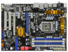
Serial ATA (SATA) Power Cable (Optional) connect to the SATA HDD power connector connect to the power supply USB 2.0 Headers (9-pin USB10_11) (see p.12 No. 26) (9-pin USB8_9) (see p.12 No. 27) TPM Header (19-pin TPM1) (see p.12 No. 21) USB_PWR P-11 P+11 GND DUMMY 1 GND P+10 P-10 USB_PWR USB_PWR P-9 P+9 GND DUMMY 1 GND P+8 P-8 USB_PWR 1 Infrared Module Header (5-pin IR1) (see p.12 No. 23) Chassis Intrusion Header (2-pin CI1) (see p.12 No. 16) IRTX +5VSB DUMMY 1 GND IRRX 1 GND Signal PCICLK FRAME PCIRST# LAD3 +3V LAD0 NC +3VSB GND PWRDWN GND NC LAD2 LAD1 GND NC SERIRQ CLKRUN NC Please connect the black end of SATA power cable to the power connector on each drive. Then connect the white end of SATA power cable to the power connector of the power supply. Besides seven default USB 2.0 ports on the I/O panel, there are two USB 2.0 headers on this motherboard. Each USB 2.0 header can support two USB 2.0 ports. This connector supports a Trusted Platform Module (TPM) system, which can securely store keys, digital certificates, passwords, and data. A TPM system also helps enhance network security, protects digital identities, and ensures platform integrity. This header supports an optional wireless transmitting and receiving infrared module. This motherboard supports CASE OPEN detection feature that detects if the chassis cover has been removed. This feature requires a chassis with chassis intrusion detection design. 28
-
 1
1 -
2
-
3
-
4
-
5
-
6
-
7
-
8
-
9
-
10
-
11
-
12
-
13
-
14
-
15
-
16
-
17
-
18
-
19
-
20
-
21
-
22
-
 23
23 -
 24
24 -
 25
25 -
 26
26 -
 27
27 -
 28
28 -
 29
29 -
 30
30 -
 31
31 -
 32
32 -
 33
33 -
34
-
35
-
36
-
37
-
38
-
39
-
40
-
41
-
42
-
43
-
44
-
45
-
46
-
47
-
48
-
49
-
50
-
51
-
52
-
53
-
54
-
55
-
56
-
57
-
58
-
59
-
60
-
61
-
62
-
63
 |
 |
