ASRock H55M-GE R2.0 User Manual
ASRock H55M-GE R2.0 Manual
 |
View all ASRock H55M-GE R2.0 manuals
Add to My Manuals
Save this manual to your list of manuals |
ASRock H55M-GE R2.0 manual content summary:
- ASRock H55M-GE R2.0 | User Manual - Page 1
H55M-GE User Manual Version 1.0 Published May 2010 Copyright©2010 ASRock INC. All rights reserved. 1 - ASRock H55M-GE R2.0 | User Manual - Page 2
any form or by any means, except duplication of documentation by the purchaser for backup purpose, without written consent of ASRock Inc. Products and corporate names appearing in this manual may or may not be registered trademarks or copyrights of their respective companies, and are used only for - ASRock H55M-GE R2.0 | User Manual - Page 3
Hard Disks Installation 26 2.11 Hot Plug Function for SATA / SATAII HDDs 26 2.12 SATA / SATAII HDD Hot Plug Feature and Operation Guide 27 2.13 Driver Installation Guide 29 2.14 Installing Windows® 7 / 7 64-bit / VistaTM / VistaTM 64-bit / XP / XP 64-bit 29 2.14.1 Installing Windows® XP / XP 64 - ASRock H55M-GE R2.0 | User Manual - Page 4
47 3.6 Boot Screen 48 3.6.1 Boot Settings Configuration 48 3.7 Security Screen 49 3.8 Exit Screen 50 4 Software Support 51 4.1 Install Operating System 51 4.2 Support CD Information 51 4.2.1 Running Support CD 51 4.2.2 Drivers Menu 51 4.2.3 Utilities Menu 51 4.2.4 Contact Information 51 4 - ASRock H55M-GE R2.0 | User Manual - Page 5
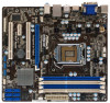
information about the model you are using. www.asrock.com/support/index.asp 1.1 Package Contents ASRock H55M-GE Motherboard (Micro ATX Form Factor: 9.6-in x 8.7-in, 24.4 cm x 22.1 cm) ASRock H55M-GE Quick Installation Guide ASRock H55M-GE Support CD 2 x Serial ATA (SATA) Data Cables (Optional - ASRock H55M-GE R2.0 | User Manual - Page 6
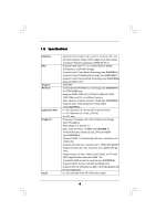
-quality Conductive Polymer Capacitors) (H55M-GE R2.0) - Supports Intel® CoreTM i7 / i5 / i3 and Pentium® G6950 Processors in LGA1156 Package - Supports Intel® Turbo Boost Technology (see CAUTION 1) - Supports Hyper-Threading Technology (see CAUTION 2) - Supports Untied Overclocking Technology (see - ASRock H55M-GE R2.0 | User Manual - Page 7
Up Events - Supports jumperfree - SMBIOS 2.3.1 Support - CPU VID, CPU GFX, VCCM, VTT, PCH PLL Voltage Multi-adjustment - Drivers, Utilities, AntiVirus Software (Trial Version), ASRock Software Suite (CyberLink DVD Suite and Creative Sound Blaster X-Fi MB) (OEM and Trial Version) - ASRock OC Tuner - ASRock H55M-GE R2.0 | User Manual - Page 8
Frequency Stepless Control (see CAUTION 16) - ASRock U-COP (see CAUTION 17) - Boot Failure Guard (B.F.G.) - Combo Cooler Option (C.C.O.) (see CAUTION 18) - Good Night LED - Turbo 50 / Turbo 100 GPU Overclocking (Requires a Processor with Intel® Graphics Technology) Hardware - CPU Temperature - ASRock H55M-GE R2.0 | User Manual - Page 9
Intel® website for the latest information. 8. You can choose to use two of the three monitors only. D-Sub, DVI-D and HDMI monitors cannot be enabled at the same time. Besides, with the DVIto-HDMI adapter, the DVI-D port can support the same features as HDMI user-friendly ASRock overclocking tool - ASRock H55M-GE R2.0 | User Manual - Page 10
you what it is capable of. OC DNA, an exclusive utility developed by ASRock, provides a convenient way for the user to record the OC settings and EuP ready motherboard and an EuP ready power supply are required. According to Intel's suggestion, the EuP ready power supply must meet the standard of 5v - ASRock H55M-GE R2.0 | User Manual - Page 11
AUDIO CODEC Super I/O COM1 1 LPT1 1 CHA_FAN1 H55M-GE PCI Express 2.0 PCIE1 Designed in Taipei DDR3 2600+ PCI1 PCIE2 CMOS Battery ErP/EuP Ready PCI2 CLRCMOS1 1 CI1 1 IR1 1 TPMS1 1 USB_PWR3 1 USB10_11 USB8_9 1 1 Intel H55 SATAII_3 SATAII_6 USB6_7 1 PANEL1 PLED PWRBTN 1 HDLED - ASRock H55M-GE R2.0 | User Manual - Page 12
(Pink) 9 8 7 7 USB 2.0 Ports (USB01) 8 USB 2.0 Ports (USB23) 9 HDMI Port 10 VGA/DVI-D Port 11 PS/2 Keyboard Port (Purple) * There are two LED next to find "VIA HD Audio Deck" tool on your system. Please follow below instructions according to the OS you install. For Windows® XP / XP 64 - ASRock H55M-GE R2.0 | User Manual - Page 13
Chapter 2: Installation This is a Micro ATX form factor (9.6" x 8.7", 24.4 x 22.1 cm) motherboard. Before you install the motherboard, study the configuration of your chassis to ensure that the motherboard fits into it. Make sure to unplug the power cord before installing or removing the motherboard - ASRock H55M-GE R2.0 | User Manual - Page 14
2.3 CPU Installation For the installation of Intel 1156-Pin CPU, please follow the steps below. Load Plate Load Lever Contact Array Socket Body 1156-Pin Socket Overview to handle and avoid kicking off the PnP cap. 2. This cap must be placed if returning the motherboard for after service. 14 - ASRock H55M-GE R2.0 | User Manual - Page 15
Step 3. Insert the 1156-Pin CPU: Step 3-1. Hold the CPU by the edge where is marked with black line. black line Step 3-2. Orient the CPU with IHS (Integrated Heat Sink) up. Locate Pin1 and the two orientation key notches. orientation key notch alignment key Pin1 Pin1 orientation key notch 1156 - ASRock H55M-GE R2.0 | User Manual - Page 16
1156-Pin socket that supports Intel 1156-Pin CPU. Please adopt the type of heatsink and cooling fan compliant with Intel 1156-Pin CPU to see page 11, No. 4). For proper installation, please kindly refer to the instruction manuals of your CPU fan and heatsink. Below is an example to illustrate the - ASRock H55M-GE R2.0 | User Manual - Page 17
2.5 Installation of Memory Modules (DIMM) This motherboard provides four 240-pin DDR3 (Double Data Rate 3) DIMM slots, and supports Dual Channel Memory Technology. For dual channel configuration, you always need to install identical (the same brand, speed, size and chiptype) DDR3 DIMM pair in - ASRock H55M-GE R2.0 | User Manual - Page 18
Installing a DIMM Please make sure to disconnect power supply before adding or removing DIMMs or the system components. Step 1. Step 2. Unlock a DIMM slot by pressing the retaining clips outward. Align a DIMM on the slot such that the notch on the DIMM matches the break on the slot. notch break - ASRock H55M-GE R2.0 | User Manual - Page 19
2.6 Expansion Slots (PCI and PCI Express Slots) There are 2 PCI slots and 2 PCI Express slots on this motherboard. PCI slot: PCI slot is used to install expansion cards that have the 32-bit PCI interface. PCIE slots: PCIE1 (PCIE x16 slot; Blue) is used for PCI Express x16 lane width graphics cards. - ASRock H55M-GE R2.0 | User Manual - Page 20
2.7 Jumpers Setup The illustration shows how jumpers are setup. When the jumper cap is placed on pins, the jumper is "Short". If no jumper cap is placed on pins, the jumper is "Open". The illustration shows a 3-pin jumper whose pin1 and pin2 are "Short" when jumper cap is placed on these 2 - ASRock H55M-GE R2.0 | User Manual - Page 21
see p.11, No. 17) (SATAII_6: see p.11, No. 19) SATAII_6 SATAII_3 SATAII_5 SATAII_2 SATAII_4 SATAII_1 These six Serial ATAII (SATAII) connectors support SATA data cables for internal storage devices. The current SATAII interface allows up to 3.0 Gb/s data transfer rate. Serial ATA (SATA) Data - ASRock H55M-GE R2.0 | User Manual - Page 22
allows convenient connection and control of audio devices. 1. High Definition Audio supports Jack Sensing, but the panel wire on the chassis must support HDA to function correctly. Please follow the instruction in our manual and chassis manual to install your system. 2. If you use AC'97 audio panel - ASRock H55M-GE R2.0 | User Manual - Page 23
connect a CPU fan cable to this connector and match the black wire to the ground pin. Though this motherboard provides 4-Pin CPU fan (Quiet Fan) support, the 3-Pin CPU fan still can work successfully even without the fan speed control function. If you plan to connect the 3-Pin CPU fan to - ASRock H55M-GE R2.0 | User Manual - Page 24
1 GND SPDIFOUT Please connect an ATX 12V power supply to this connector. This COM1 header supports a serial port module. HDMI_SPDIF header, providing SPDIF audio output to HDMI VGA card, allows the system to connect HDMI Digital TV/ projector/LCD devices. Please connect the HDMI_SPDIF connector of - ASRock H55M-GE R2.0 | User Manual - Page 25
guide. Some default setting of SATAII hard disks may not be at SATAII mode, which operate with the best performance. In order to enable SATAII function, please follow the below instruction 's website for details: http://www.hitachigst.com/hdd/support/download.htm The above examples are just for your - ASRock H55M-GE R2.0 | User Manual - Page 26
(SATAII) Hard Disks Installation This motherboard adopts Intel® H55 bridge chipset that supports Serial ATA (SATA) / Serial ATAII (SATAII) hard disks. You may install SATA / SATAII hard disks on this motherboard for internal storage devices. This section will guide you to install the SATA / SATAII - ASRock H55M-GE R2.0 | User Manual - Page 27
is installed into system properly. The latest SATA / SATAII driver is available on our support website: www.asrock.com 4. Make sure to use the SATA power cable & data cable, which are from our motherboard package. 5. Please follow below instructions step by step to reduce the risk of HDD crash or - ASRock H55M-GE R2.0 | User Manual - Page 28
the SATA / SATAII HDD. How to Hot Unplug a SATA / SATAII HDD: Points of attention, before you process the Hot Unplug: Please do follow below instruction sequence to process the Hot Unplug, improper procedure will cause the SATA / SATAII HDD damage and data loss. Step 1 Unplug SATA data cable from - ASRock H55M-GE R2.0 | User Manual - Page 29
2.13 Driver Installation Guide To install the drivers to your system, please insert the support CD to your optical drive first. Then, the drivers compatible to your system can be auto-detected and listed on the support CD driver page. Please follow the order from up to bottom side to install those - ASRock H55M-GE R2.0 | User Manual - Page 30
OS on your system. 2.15 Untied Overclocking Technology This motherboard supports Untied Overclocking Technology, which means during overclocking, FSB enjoys better option of BIOS setup to set the selection from [Auto] to [Manual]. Therefore, CPU FSB is untied during overclocking, but PCI / PCIE - ASRock H55M-GE R2.0 | User Manual - Page 31
SETUP UTILITY when you start up the computer. Please press or during the Power-On-Self-Test (POST) to enter the BIOS SETUP UTILITY, otherwise, POST will continue with its test routines. If you wish to enter the BIOS SETUP UTILITY after POST, restart the system by pressing + - ASRock H55M-GE R2.0 | User Manual - Page 32
Monitor Boot Security Exit System Overview System Time System Date [14:00:09] [Fri 05/14/2010] BIOS Version : H55M-GE P1.00 Processor Type : Intel (R) Core (TM) i5 CPU K 655 @ 3.20GHz (64bit) Processor Speed : 3200MHz Microcode Update : 20655/2 Cache Size : 4096KB Total Memory DDR3_A2 - ASRock H55M-GE R2.0 | User Manual - Page 33
ESC Exit v02.54 (C) Copyright 1985-2005, American Megatrends, Inc. Turbo 50 You can use this option to increase your system performance. If you adopt Intel® Pentium® G6950 CPU, this option will be "Turbo 100". Load CPU EZ OC Setting You can use this option to load CPU EZ overclocking setting - ASRock H55M-GE R2.0 | User Manual - Page 34
. The default value is [Disabled]. Overclock Mode Use this to select Overclock Mode. Configuration options: [Auto], [Manual] and [Optimized]. The default value is [Auto]. If you select [Manual], Untied Overclocking function is enabled. Please refer to page 30 for the details of Untied Overclocking - ASRock H55M-GE R2.0 | User Manual - Page 35
DRAM Timing Control Use this item to control DRAM Timing. Advanced DRAM Timing Control DRAM tCL DRAM tRCD DRAM tRP DRAM tRAS DRAM tRFC DRAM tWR DRAM tWTR DRAM tRRD DRAM tRTP DRAM tFAW DRAM Command Rate BIOS SETUP UTILITY 9 [Auto] 9 [Auto] 9 [Auto] 24 [Auto] 74 [Auto] 10 [Auto] 5 [Auto] 4 [Auto] 5 - ASRock H55M-GE R2.0 | User Manual - Page 36
to adjust DRAM Command Rate. Configuration options : [Auto], [1] and [2]. CPU Voltage Use this to select CPU Voltage. Configuration options: [Auto], [Manual] and [Overdrive Offset]. The default value is [Auto]. DRAM Voltage Use this to select DRAM Voltage. Configuration options: [Auto], [1.300V] to - ASRock H55M-GE R2.0 | User Manual - Page 37
other complicated flash utility. Please be noted that the USB flash drive or hard drive must use FAT32/16/ 12 file system. If you execute ASRock Instant Flash utility, the utility will show the BIOS files and their respective information. Select the proper BIOS file to update your BIOS, and reboot - ASRock H55M-GE R2.0 | User Manual - Page 38
Halt State (C1). The C1 state is supported through the native processor instructions HLT and MWAIT and requires no hardware support from the chipset. In the C1 power state, the processor maintains the context of the system caches. Intel (R) Virtualization tech. When this option is set to [Enabled - ASRock H55M-GE R2.0 | User Manual - Page 39
/ 7 and want to enable this function, please set this item to [Enabled]. This item will be hidden if the current CPU does not support Intel (R) SpeedStep(tm) tech.. Please note that enabling this function may reduce CPU voltage and lead to system stability or compatibility issue with some power - ASRock H55M-GE R2.0 | User Manual - Page 40
Front Panel Onboard HDMI HD Audio OnBoard Lan [PCI] [Auto] [DVMT Mode] [Maximum DVMT] [Auto] [Auto] [Enabled] [Enabled] Intel VT-d Configuration + not be used under Windows® VistaTM / 7 OS because the driver will intelligently detect physical memory available and allocate necessary video memory. - ASRock H55M-GE R2.0 | User Manual - Page 41
"OnBoard Lan" feature. Intel VT-d Configuration Use this to enable or disable Intel® VT-d technology (Intel® Virtualization Technology for Directed Suspend-toRAM feature. Select [Auto] will enable this feature if the OS supports it. Check Ready Bit Use this item to enable or disable the feature - ASRock H55M-GE R2.0 | User Manual - Page 42
"SATAII 5,6 Configuration" will appear. If you select [AHCI] mode, the options "Hot Plug" and "Link Power Management" will appear. AHCI (Advanced Host Controller Interface) supports NCQ and other new features that will improve SATA disk performance but IDE mode does not have these advantages. 42 - ASRock H55M-GE R2.0 | User Manual - Page 43
use the "Primary IDE Master" as the example in the following instruction. BIOS SETUP UTILITY Advanced Primary IDE Master Device Vendor Size LBA Mode Data Transfer :Hard Disk :ST340014A :40.0 GB :Supported :16Sectors :4 :MultiWord DMA-2 :Ultra DMA-5 :Supported [Auto] [Auto] [Auto] [Auto] [Auto] - ASRock H55M-GE R2.0 | User Manual - Page 44
DMA Mode DMA capability allows the improved transfer-speed and data-integrity for compatible IDE devices. S.M.A.R.T. Use this item to enable or disable the S.M.A.R.T. (Self-Monitoring, Analysis, and Reporting Technology) feature. Configuration options: [Disabled], [Auto], [Enabled]. 32-Bit Data - ASRock H55M-GE R2.0 | User Manual - Page 45
3.4.6 Super IO Configuration BIOS SETUP UTILITY Advanced Configure Super IO Chipset Serial Port Address Infrared Port Address Parallel Port Address Parallel Port Mode EPP Version ECP Mode DMA Channel Parallel Port IRQ PS/2 Port Type [3F8 / IRQ4] [Disabled] [378] [ECP + EPP] [1.9] [DMA3] [IRQ7] [ - ASRock H55M-GE R2.0 | User Manual - Page 46
-2005, American Megatrends, Inc. USB Controller Use this item to enable or disable the use of USB controller. Legacy USB Support Use this option to select legacy support for USB devices. There are four configuration options: [Enabled], [Auto], [Disabled] and [BIOS Setup Only]. The default value is - ASRock H55M-GE R2.0 | User Manual - Page 47
mode]. The default is value [Full On]. Chassis Fan Setting This allows you to set the chassis fan speed. Configuration options: [Full On] and [Manual mode]. The default is value [Full On]. Case Open Feature This allows you to enable or disable case open detection feature. The default is value - ASRock H55M-GE R2.0 | User Manual - Page 48
Help Load Defaults Save and Exit Exit v02.54 (C) Copyright 1985-2003, American Megatrends, Inc. Full Screen Logo Use this item to enable or disable OEM Logo. The default value is [Enabled]. AddOn ROM Display Use this option to adjust AddOn ROM Display. If you enable the option "Full Screen Logo - ASRock H55M-GE R2.0 | User Manual - Page 49
to select logo in POST screen. This option only appears when you enable the option "Full Screen Logo". Configuration options: [Auto], [EuP], [Scenery] and [ASRock]. The default value is [Auto]. Boot From Onboard LAN Use this item to enable or disable the Boot From Onboard LAN feature. Boot Up Num - ASRock H55M-GE R2.0 | User Manual - Page 50
3.8 Exit Screen BIOS SETUP UTILITY Main OC Tweaker Advanced H/W Monitor Boot Security Exit Exit Options Save Changes and Exit Discard Changes and Exit Discard Changes Load BIOS Defaults Load Performance Setup Default (IDE/SATA) Load Performance Setup AHCI Mode Load Power Saving Setup Default Exit - ASRock H55M-GE R2.0 | User Manual - Page 51
install the necessary drivers to activate the devices. 4.2.3 Utilities Menu The Utilities Menu shows the applications software that the motherboard supports. Click on a specific item then follow the installation wizard to install it. 4.2.4 Contact Information If you need to contact ASRock or want to
-
 1
1 -
 2
2 -
 3
3 -
 4
4 -
 5
5 -
 6
6 -
 7
7 -
8
-
9
-
10
-
11
-
12
-
13
-
14
-
15
-
16
-
17
-
18
-
19
-
20
-
21
-
22
-
23
-
24
-
25
-
26
-
27
-
28
-
29
-
30
-
31
-
32
-
33
-
34
-
35
-
36
-
37
-
38
-
39
-
40
-
41
-
42
-
43
-
44
-
45
-
46
-
47
-
48
-
49
-
50
-
51
 |
 |

1
H55M-GE
User Manual
Version 1.0
Published May 2010
Copyright©2010 ASRock INC. All rights reserved.