ASRock H55M-LE Quick Installation Guide
ASRock H55M-LE Manual
 |
View all ASRock H55M-LE manuals
Add to My Manuals
Save this manual to your list of manuals |
ASRock H55M-LE manual content summary:
- ASRock H55M-LE | Quick Installation Guide - Page 1
' benefit, without intent to infringe. Disclaimer: Specifications and information contained in this guide are furnished for informational use only and subject ASRock Website: http://www.asrock.com Published January 2010 Copyright©2010 ASRock INC. All rights reserved. 1 ASRock H55M-LE Motherboard - ASRock H55M-LE | Quick Installation Guide - Page 2
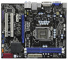
16 Clear CMOS Jumper (CLRCMOS1) 2 PS2_USB_PWR1 Jumper 17 Chassis Fan Connector (CHA_FAN1) 3 CPU Fan Connector (CPU_FAN1) 18 USB 2.0 Header (USB6_7, Blue) 4 Power Fan Connector (PWR_FAN1) 19 USB_PWR1 (PORT 6-9) Jumper 5 1156-Pin CPU Socket 20 USB 2.0 Header (USB8_9, Blue) 6 2 x 240-pin DDR3 - ASRock H55M-LE | Quick Installation Guide - Page 3
accordance with the type of speaker you use. TABLE for Audio Output Connection Audio Output Channels Front Speaker Rear Speaker Central / Bass Side Speaker (No. 7) (No. 4) (No. 5) (No. 3) 2 V -- -- -- 4 V V -- -- 6 V V V -- 8 V V V V 3 ASRock H55M-LE Motherboard English - ASRock H55M-LE | Quick Installation Guide - Page 4
item "Independent Headphone". For Windows® 7 / 7 64-bit / VistaTM / VistaTM 64-bit OS: Please click "VIA HD Audio Deck" icon. Click "Advanced Options" on the right side on the bottom. In "Advanced Options" screen, please check the item "Independent Headphone". 4 ASRock H55M-LE Motherboard English - ASRock H55M-LE | Quick Installation Guide - Page 5
visit our website for specific information about the model you are using. www.asrock.com/support/index.asp 1.1 Package Contents ASRock H55M-LE Motherboard (Micro ATX Form Factor: 9.6-in x 8.0-in, 24.4 cm x 20.3 cm) ASRock H55M-LE Quick Installation Guide ASRock H55M-LE Support CD 2 x Serial ATA - ASRock H55M-LE | Quick Installation Guide - Page 6
1.2 Specifications Platform CPU Chipset Memory Expansion Slot Graphics * Audio LAN - Micro ATX Form Factor: 9.6-in x 8.0-in, 24.4 cm x 20.3 cm - Solid Capacitor for CPU power - Supports Intel® CoreTM i7 / i5 / i3 and Pentium® G6950 Processors in LGA1156 Package - Supports Intel® Turbo Boost - ASRock H55M-LE | Quick Installation Guide - Page 7
10) - 16Mb AMI Legal BIOS - Supports "Plug and Play" - ACPI 1.1 Compliance Wake Up Events - Supports jumperfree - SMBIOS 2.3.1 Support - CPU, DRAM, VTT, PCH, CPU PLL, GFX Voltage Multi-adjustment - Drivers, Utilities, AntiVirus Software (Trial Version), ASRock Software Suite (CyberLink DVD Suite - ASRock H55M-LE | Quick Installation Guide - Page 8
Night LED - Turbo 50 / Turbo 100 GPU Overclocking (Requires a Processor with Intel® Graphics Technology) Hardware - CPU Temperature Sensing Monitor - Chassis Temperature Sensing - CPU/Chassis/Power Fan Tachometer - CPU Quiet Fan - CPU/Chassis Fan Multi-Speed Control - CASE OPEN detection - ASRock H55M-LE | Quick Installation Guide - Page 9
/ XP. For Windows® OS with 64-bit CPU, there is no such limitation. 6. For those CPU that only support up to DDR3 1333, the XMP DDR3 1600 is supported through overclocking. 7. The maximum shared memory size is defined by the chipset vendor and is subject to change. Please check Intel® website - ASRock H55M-LE | Quick Installation Guide - Page 10
Intel's suggestion, the EuP ready power supply must meet the standard of 5v standby power efficiency is higher than 50% under 100 mA current consumption. For EuP ready power supply selection, we recommend you checking with the power supply manufacturer for more details. 10 ASRock H55M-LE Motherboard - ASRock H55M-LE | Quick Installation Guide - Page 11
Before you insert the 1156-Pin CPU into the socket, please check if the CPU surface is unclean or if there is any bent pin on the socket. Do not force to insert the CPU into the socket if above situation is found. Otherwise, the CPU will be seriously damaged. 11 ASRock H55M-LE Motherboard English - ASRock H55M-LE | Quick Installation Guide - Page 12
key notches. orientation key notch alignment key Pin1 Pin1 orientation key notch alignment key 1156-Pin Socket 1156-Pin CPU For proper inserting, please ensure to match the two orientation key notches of the CPU with the two alignment keys of the socket. 12 ASRock H55M-LE Motherboard - ASRock H55M-LE | Quick Installation Guide - Page 13
other components. et Please be noticed that this motherboard supports Combo Cooler Option (C.C.O.), which provides the flexible option to adopt two different CPU cooler types, Socket LGA 775 and LGA 1156. The white throughholes are for Socket LGA 1156 CPU fan. 13 ASRock H55M-LE Motherboard English - ASRock H55M-LE | Quick Installation Guide - Page 14
H55M-LE motherboard provides two 240-pin DDR3 (Double Data Rate 3) DIMM slots, and supports a DDR or DDR2 memory module into DDR3 slot;otherwise, this motherboard and DIMM may be damaged. 2. If orientation. It will cause permanent damage to the motherboard and the DIMM if you force the DIMM into - ASRock H55M-LE | Quick Installation Guide - Page 15
slot that you intend to use. Keep the screws for later use. Step 4. Align the card connector with the slot and press firmly until the card is completely seated on the slot. Step 5. Fasten the card to the chassis with screws. Step 6. Replace the system cover. 15 ASRock H55M-LE Motherboard English - ASRock H55M-LE | Quick Installation Guide - Page 16
the BIOS, you must boot up the system first, and then shut it down before you do the clearCMOS action. If you clear the CMOS, the case open may be detected. Please adjust the BIOS option "Clear Status" to clear the record of previous chassis intrusion status. English 16 ASRock H55M-LE Motherboard - ASRock H55M-LE | Quick Installation Guide - Page 17
I/O panel, there are two USB 2.0 headers on this motherboard. Each USB 2.0 header can support two USB 2.0 ports. Print Port Header (25-pin LPT1) (see p.2 No. 23) This is an interface for print port cable that allows convenient connection of printer devices. English 17 ASRock H55M-LE Motherboard - ASRock H55M-LE | Quick Installation Guide - Page 18
audio devices. 1. High Definition Audio supports Jack Sensing, but the panel wire on the chassis must support HDA to function correctly. Please follow the instruction in our manual and chassis manual to p.2 No. 14) Please connect the chassis speaker to this header. 18 ASRock H55M-LE Motherboard - ASRock H55M-LE | Quick Installation Guide - Page 19
Power Supply Installation 1 13 Please connect an ATX 12V power supply to this connector. Serial port Header (9-pin COM1) (see p.2 No.24) This COM1 header supports a serial port module. English 19 ASRock H55M-LE Motherboard - ASRock H55M-LE | Quick Installation Guide - Page 20
HDMI VGA card to this header. Please connect the black end (A) of HDMI_SPDIF cable to the HDMI_SPDIF header on the motherboard. Then connect the white end (B or C) of HDMI_SPDIF cable to the HDMI_SPDIF connector of HDMI VGA card. B. white end (2-pin) C. white end (3-pin) English 20 ASRock H55M-LE - ASRock H55M-LE | Quick Installation Guide - Page 21
HDDs without NCQ function (IDE mode) STEP 1: Set up BIOS. A. Enter BIOS SETUP UTILITY Advanced screen Storage Configuration. B. Set the option "SATA Operation Mode" to [IDE]. STEP 2: Install Windows® 7 / 7 64-bit / VistaTM / VistaTM 64-bit OS on your system. 21 ASRock H55M-LE Motherboard English - ASRock H55M-LE | Quick Installation Guide - Page 22
Technology This motherboard supports Untied Overclocking Technology, which means during overclocking, FSB enjoys better margin due to fixed PCI / PCIE buses. Before you enable Untied Overclocking function, please enter "Overclock Mode" option of BIOS setup to set the selection from [Auto] to [Manual - ASRock H55M-LE | Quick Installation Guide - Page 23
the User Manual (PDF file) contained in the Support CD. 4. Software Support CD information This motherboard supports various Microsoft® Windows® operating systems: 7 / 7 64-bit / VistaTM / VistaTM 64-bit / XP / XP 64-bit. The Support CD that came with the motherboard contains necessary drivers and - ASRock H55M-LE | Quick Installation Guide - Page 24
.asrock.com/support/index.asp 1.1 Kartoninhalt ASRock H55M-LE Motherboard (Micro ATX-Formfaktor: 24.4 cm x 20.3 cm; 9.6 Zoll x 8.0 Zoll) ASRock H55M-LE Schnellinstallationsanleitung ASRock H55M-LE Support-CD Zwei Serial ATA (SATA) -Datenkabel (optional) Ein I/O Shield 24 ASRock H55M-LE Motherboard - ASRock H55M-LE | Quick Installation Guide - Page 25
CPU - Intel® H55 - Unterstützung von Dual-Kanal-Speichertechnologie (siehe VORSICHT 4) - 2 x Steckplätze für DDR3 - Unterstützt DDR3 2600+(OC)/2133(OC)/1866(OC)/1600/ 1333/1066 non-ECC, ungepufferter Speicher - Max. Kapazität des Systemspeichers: 8GB DVI-Port Deutsch 25 ASRock H55M-LE Motherboard - ASRock H55M-LE | Quick Installation Guide - Page 26
üsse an der Rückseite Anschlüsse BIOS Support-CD Einzigartige Eigenschaft - 7.1 CH HD Audio (VIA® VT1718S Audio Codec) - PCIE x1 Gigabit LAN 10/100/1000 Mb/s - Realtek RTL8111DL - Unterstützt Wake-On-LAN I/O Panel - 1 x PS/2-Tastaturanschluss - 1 x VGA/D-Sub port - 1 x VGA/DVI-D port - 6 x Standard - ASRock H55M-LE | Quick Installation Guide - Page 27
CPU-/ Gehäuselüfter - GEHÄUSE OFFEN-Erkennung - Spannungsüberwachung: +12V, +5V, +3.3V, Vcore Betriebssysteme - Unterstützt Microsoft® Windows® 7 / 7 64-Bit / VistaTM / VistaTM 64-Bit / XP / XP mögliche Schäden, die aufgrund von Overclocking verursacht wurden. 27 ASRock H55M-LE Motherboard Deutsch - ASRock H55M-LE | Quick Installation Guide - Page 28
und Ihre Hardware-Geräte übertakten, um die beste Systemleistung unter der Windows® Umgebung zu erreichen. Besuchen Sie bitte unsere Website für die Operationsverfahren von ASRock OC Tuner. ASRock-Website: http://www.asrock.com/feature/OCTuner/index.htm 28 ASRock H55M-LE Motherboard Deutsch - ASRock H55M-LE | Quick Installation Guide - Page 29
üfen Sie bitte, ob der CPU-Lüfter am Motherboard richtig funktioniert, und stecken Sie bitte den Stromkabelstecker aus und dann wieder ein. Um die Wärmeableitung zu verbessern, bitte nicht vergessen, etwas Wärmeleitpaste zwischen CPU und Kühlkörper zu sprühen. 29 ASRock H55M-LE Motherboard Deutsch - ASRock H55M-LE | Quick Installation Guide - Page 30
zwei verschiedenen CPU-Kühlertypen, Socket LGA 775 und LGA 1156. Beachten Sie bitte, dass nicht alle 775 CPU-Lüfter verwendet EuP-fähiges Motherboard und eine EuP-fähige Stromversorgung erforderlich. Gemäß einer Empfehlung von Intel muss eine EuP abzufragen. 30 ASRock H55M-LE Motherboard Deutsch - ASRock H55M-LE | Quick Installation Guide - Page 31
) 1156-Pin Sockel Übersicht Bevor Sie die 1156-Pin CPU in den Sockel sitzen, prüfen Sie bitte, ob die CPU-Oberfläche sauber ist und keine der Kontakte verbogen sind. Setzen Sie die CPU nicht mit Gewalt in den Sockel, dies kann die CPU schwer beschädigen. Deutsch 31 ASRock H55M-LE Motherboard - ASRock H55M-LE | Quick Installation Guide - Page 32
Teil mit dem IHS (Integrated Heat Sink - integrierter Kühlkörper) nach oben. Suchen Sie Pin 1 und die zwei Orientierungseinkerbungen. Orientierungskerbe Ausrichtungsmarkierung Pin1 Pin1 Ausrichtungsmarkierung Orientierungskerbe 1156-Pin Sockel 1156-Pin CPU 32 ASRock H55M-LE Motherboard - ASRock H55M-LE | Quick Installation Guide - Page 33
. Schritt 3-3. Drücken Sie die CPU vorsichtig in vertikaler Richtung in den Sockel. Schritt 3-4. Prüfen Sie, dass die CPU ordnungsgemäß im Sockel sitzt und die Ladehebel. Schritt 4-3. Sichern Sie Ladehebel und Ladeplatte mithilfe des Hebelverschlusses. 33 ASRock H55M-LE Motherboard Deutsch - ASRock H55M-LE | Quick Installation Guide - Page 34
, dass dieses Motherboard die ComboKühleroption unterstützt, die eine flexible Möglichkeit zur Aufnahme von zwei verschiedenen CPU-Kühlertypen, Socket LGA 775 und LGA 1156, bietet. Das weiße Durchgangsloch ist für den CPULüfter im Socket LGA 1156 vorgesehen. 34 ASRock H55M-LE Motherboard Deutsch - ASRock H55M-LE | Quick Installation Guide - Page 35
H55M-LE Motherboard bietet zwei 240polige DDR3 (Double Data Rate 3) DIMM-Steckplätze und unterstützt Zweikanal-Speichertechnologie. Es müssen immer zwei identische Speichermodule (selbe Marke, Geschwindigkeit, Größe und Chip-Art) in den DDR3 fest an Ort und Stelle sitzt. 35 ASRock H55M-LE Motherboard - ASRock H55M-LE | Quick Installation Guide - Page 36
Steckplätze) Es gibt einen 2 PCI-Steckplätze und 2 PCI Express-Steckplätze am H55M-LE Motherboard. PCI-Slots: PCI-Slots werden zur Installation von Erweiterungskarten mit dem 32bit PCI-Interface genutzt 4: Befestigen Sie die Karte mit der Schraube aus Schritt 2. 36 ASRock H55M-LE Motherboard Deutsch - ASRock H55M-LE | Quick Installation Guide - Page 37
vergessen Sie nicht, den Jumper wieder zu entfernen, nachdem das CMOS gelöscht wurde. Wenn Sie den CMOSInhalt gleich nach dem Aktualisieren des BIOS löschen müssen, müssen Sie zuerst das System starten und dann wieder ausschalten, bevor Sie den CMOS-Inhalt löschen. 37 ASRock H55M-LE Motherboard - ASRock H55M-LE | Quick Installation Guide - Page 38
CMOS kann erkannt werden, wenn das Gehäuse offen ist. Bitte stellen Sie zum Löschen der Aufzeichnung des vorherigen Gehäuseindringungsstatus die BIOS- USB 2.0Anschlussleisten am Motherboard. Pro USB 2.0Anschlussleiste werden zwei USB 2.0-Ports unterstützt. Deutsch 38 ASRock H55M-LE Motherboard - ASRock H55M-LE | Quick Installation Guide - Page 39
uses, ermöglicht Ihnen eine bequeme Anschlussmöglichkeit und Kontrolle über Audio-Geräte. 1. High Definition Audio unterstützt Jack Sensing (automatische Erkennung falsch angeschlossener Geräte), ßen Sie Audio_R (RIN) an OUT2_R und Audio_L (LIN) an OUT2_L an. 39 ASRock H55M-LE Motherboard Deutsch - ASRock H55M-LE | Quick Installation Guide - Page 40
werden. E. Rufen Sie das BIOS-Setup-Dienstprogramm auf. Wechseln Sie CPU-Lüfter an den CPU-Lüferanschluss dieses Motherboards anschließen möchten, verbinden Sie ihn bitte mit den Pins 1 - 3. Pins 1-3 anschließen Lüfter mit dreipoligem Anschluss installieren Deutsch 40 ASRock H55M-LE Motherboard - ASRock H55M-LE | Quick Installation Guide - Page 41
No. 7) 12 24 Verbinden Sie die ATXStromversorgung mit diesem Header. 1 13 Obwohl dieses Motherboard einen 24-pol. ATX-Stromanschluss 12 24 bietet, kann es auch mit einem modifizierten traditionellen -Anschluss der HDMI-VGA-Karte mit diesem Anschluss. 41 ASRock H55M-LE Motherboard Deutsch - ASRock H55M-LE | Quick Installation Guide - Page 42
64-Bit / XP / XP 64-Bit installieren Wenn Sie Windows® 7 / 7 64-Bit / VistaTM / VistaTM 64-Bit / XP / XP 64-Bit auf Ihren SATA / SATAII-Festplatten installieren, dann folgen Sie bitte je nach dem zu installierenden Betriebssystem den folgenden Schritten. Deutsch 42 ASRock H55M-LE Motherboard - ASRock H55M-LE | Quick Installation Guide - Page 43
Rufen Sie das BIOS SETUP UTILITY auf, wählen Sie den „Advanced"- Bildschirm (Erweitert), dann „Storage Configuration". B. Stellen Sie "SATA Operation Mode" auf [AHCI]. SCHRITT 2: Installieren Sie Windows® 7 / 7 64-Bit / VistaTM / VistaTM 64-Bit in Ihrem System. 43 ASRock H55M-LE Motherboard Deutsch - ASRock H55M-LE | Quick Installation Guide - Page 44
zum BIOS-Setup, siehe bitte das Benutzerhandbuch (PDF Datei) auf der Support CD. 4. Software Support CD information Dieses Motherboard unterstützt eine Reiche von Microsoft® Windows® Betriebssystemen: 7 / 7 64-Bit / VistaTM / VistaTM 64-Bit / XP / XP 64-Bit. Die Ihrem Motherboard beigefügte Support - ASRock H55M-LE | Quick Installation Guide - Page 45
du paquet Carte mère ASRock H55M-LE (Facteur de forme Micro ATX: 9.6 pouces x 8.0 pouces, 24.4 cm x 20.3 cm) Guide d'installation rapide ASRock H55M-LE CD de soutien ASRock H55M-LE Deux câbles de données de série ATA (SATA) (en option) Un I/O Panel Shield 45 ASRock H55M-LE Motherboard Français - ASRock H55M-LE | Quick Installation Guide - Page 46
ATTENTION 2) - Prend en charge la technologie Untied Overclocking (voir ATTENTION 3) - Prise en charge de la technologie EM64T par le CPU - Intel® H55 - Compatible avec la Technologie de Mémoire à Canal Double (voir ATTENTION 4) - 2 x slots DIMM DDR3 - Supporter DDR3 2600+(OC)/2133(OC)/1866(OC)/1600 - ASRock H55M-LE | Quick Installation Guide - Page 47
- Support SMBIOS 2.3.1 - CPU, DRAM, VTT, PCH, CPU PLL, GFX Tension Multi-ajustement - Pilotes, utilitaires, logiciel anti-virus (Version d'essai), Suite logicielle ASRock (CyberLink DVD Suite et Creative Sound Blaster X-Fi MB) (Version OEM et d'essai) Français 47 ASRock H55M-LE Motherboard - ASRock H55M-LE | Quick Installation Guide - Page 48
affecter la stabilité de votre système, ou même causer des dommages aux composants et dispositifs de votre système. Si vous le faites, c'est à vos frais et vos propres risques. Nous ne sommes pas responsables des dommages possibles causés par l'overclocking. Français 48 ASRock H55M-LE Motherboard - ASRock H55M-LE | Quick Installation Guide - Page 49
de matériels pour obtenir les meilleures performances du système sous environnement Windows®. S'il vous plaît visitez notre site web pour le fonctionnement des procédures de Tuner ASRock OC. ASRock website: http://www.asrock.com/feature/OCTuner/index.htm 49 ASRock H55M-LE Motherboard Français - ASRock H55M-LE | Quick Installation Guide - Page 50
de l'installation du PC. 17. Le Combo Cooler Option (C.C.O.) offre un choix flexible pour adopter deux types différents de refroidisseur sde CPU, les sockets LGA 775 et LGA 1156. Veuillez noter que tous les ventilateurs de CPU 775 ne peuvent pas être utilisés. 50 ASRock H55M-LE Motherboard Français - ASRock H55M-LE | Quick Installation Guide - Page 51
conforme à la norme EuP, une carte mère EuP et une alimentation EuP sont requises. Selon les suggestions d'Intel', l'alimentation électrique EuP doit correspondre à la norme, qui est que l'efficacité électrique de fournisseur de courant pour plus de détails. 51 ASRock H55M-LE Motherboard Français - ASRock H55M-LE | Quick Installation Guide - Page 52
broches dans le socket, veuillez vérifier que la surface du processeur est bien propre, et qu'il n'y a aucune broche tordue sur le socket. Si c'est le cas, ne forcez pas pour insérer le processeur dans le socket. Sinon, le processeur sera gravement endommagé. Français 52 ASRock H55M-LE Motherboard - ASRock H55M-LE | Quick Installation Guide - Page 53
3-2. Orientez le paquet avec le dissipateur thermique intégré (IHS) vers le haut. Repérez la broche 1 et les deux encoches d'orientation. Encoche d'orientation broche 1 Détrompeur Encoche d'orientation Processeur 1156 broches Détrompeur Socket 1156 broches ASRock H55M-LE Motherboard broche - ASRock H55M-LE | Quick Installation Guide - Page 54
thermique. L'exemple ci-dessous illustre l'installation du dissipateur thermique pour un processeur 1366 broches. (Appliquez le matériau d'interface thermique) Etape 1. Appliquez le matériau d'interface thermique au centre de IHS sur la surface du socket. Français 54 ASRock H55M-LE Motherboard - ASRock H55M-LE | Quick Installation Guide - Page 55
re prend en charge l'option Combo Cooler Option (C.C.O.), qui offre un choix flexible pour adopter deux types différents de refroidisseurs de CPU, les sockets LGA 775 et LGA 1156. Les trous traversant blancs sont pour le ventilateur de CPU au socket LGA 1156. Français 55 ASRock H55M-LE Motherboard - ASRock H55M-LE | Quick Installation Guide - Page 56
) dans les emplacements DDR3 DIMM pour activer la technologie Dual Channel Memory. Sinon, le système le module DIMM dans son emplacement jusqu'à ce que les clips de maintien situés aux deux extrémités se ferment complètement et que le module DIMM soit inséré correctement. ASRock H55M-LE Motherboard - ASRock H55M-LE | Quick Installation Guide - Page 57
que vous voulez utiliser. Gardez la vis pour un usage ultérieur. Etape 3. Alignez la carte sur le connecteur et appuyez fermement jusqu'à l'insertion complète de la carte dans son emplacement. Etape 4. Fixez la carte sur le châssis à l'aide d'une vis. 57 ASRock H55M-LE Motherboard Français - ASRock H55M-LE | Quick Installation Guide - Page 58
capuchon de cavalier pour courtcircuiter la broche 2 et la broche 3 sur CLRCMOS1 pendant 5 secondes. Après avoir court-circuité le cavalier Effacer la CMOS, veuillez enlever le capuchon de cavalier. Toutefois, veuillez ne pas effacer la CMOS tout de suite après avoir 58 ASRock H55M-LE Motherboard - ASRock H55M-LE | Quick Installation Guide - Page 59
avez fini de mettre le BIOS à jour, vous devez d'abord initialiser le système, puis le mettre hors tension avant de procéder à l'opération d'effacement de la CMOS. Si vous effacez la CMOS, il se peut qu'une ouverture du boîtier soit détectée. Veuillez ajuster l'option du BIOS "Clear Status" (Effacer - ASRock H55M-LE | Quick Installation Guide - Page 60
audio HD. Vous n'avez pas besoin de les connecter pour le panneau audio AC'97. E. Entrer dans l'utilitaire de configuration du BIOS. Saisir les Paramètres avancés puis sélectionner Configuration du jeu de puces. Définir l'option panneau de commande de [Auto] à [Activé]. 60 ASRock H55M-LE Motherboard - ASRock H55M-LE | Quick Installation Guide - Page 61
carte mère, veuillez le connecter aux broches 1-3. Installation de ventilateur à 3 broches Broches 1-3 connectées En-tête d'alimentation ATX (ATXPWR1 br. 24) (voir p.2 No. 7) 12 24 Veuillez connecter l'unité d'alimentation ATX sur cet entête. 1 13 Français 61 ASRock H55M-LE Motherboard - ASRock H55M-LE | Quick Installation Guide - Page 62
Connecteur HDMI_SPDIF (HDMI_SPDIF1 3-pin) (voir p.2 No. 29) Connecteur HDMI_SPDIF, fournissant une sortie audio SPDIF vers la carte VGA HDMI, et permettant au système de se connecter au un B. extrémité blanche (2 briches) C. extrémité blanche (3 briches) 62 ASRock H55M-LE Motherboard Français - ASRock H55M-LE | Quick Installation Guide - Page 63
7 64-bit / VistaTM / VistaTM 64-bit Si vous voulez installer Windows® 7 / 7 64-bit / VistaTM / VistaTM 64-bit sur vos disques durs SATA / SATAII, veuillez suivre la procédure ci-dessous. Utilisation des disques durs SATA / SATAII sans NCQ fonctions (mode IDE) 63 ASRock H55M-LE Motherboard Français - ASRock H55M-LE | Quick Installation Guide - Page 64
le BIOS. A. Accédez à BIOS SETUP UTILITY (Utilitaire de configuration BIOS) écran Avancé Configuration Storage. B. Réglez «SATA Operation Mode « sur [AHCI]. ETAPE 2: Installer le système d'exploitation Windows® 7 / 7 64-bit / VistaTM / VistaTM 64-bit sur votre système. 64 ASRock H55M-LE Motherboard - ASRock H55M-LE | Quick Installation Guide - Page 65
taillées sur le BIOS, veuillez consulter le Guide de l'utilisateur (fichier PDF) dans le CD technique. 4. Informations sur le CD de support Cette carte mère supporte divers systèmes d'exploitation Microsoft® Windows®: 7 / 7 64 bits / VistaTM / VistaTM 64 bits / XP / XP 64 bits. Le CD technique livr - ASRock H55M-LE | Quick Installation Guide - Page 66
/support/index.asp 1.1 Contenuto della confezione Scheda madre ASRock H55M-LE (Micro ATX Form Factor: 9.6-in x 8.0-in, 24.4 cm x 20.3 cm) Guida di installazione rapida ASRock H55M-LE CD di supporto ASRock H55M-LE Due cavi dati Serial ATA (SATA) (opzionali) Un I/O Shield 66 ASRock H55M-LE Motherboard - ASRock H55M-LE | Quick Installation Guide - Page 67
Supporto della funzione HDCP con le porte DVI - Supporto 1080p Blu-ray (BD) / HD-DVD riproduzione con le porte DVI Audio - 7.1 Audio HD CH (VIA® VT1718S Audio Codec) LAN - PCIE x1 Gigabit LAN 10/100/1000 Mb/s - Realtek RTL8111DL - Supporta Wake-On-LAN 67 ASRock H55M-LE Motherboard Italiano - ASRock H55M-LE | Quick Installation Guide - Page 68
Fi MB) (OEM e Versione demo) - Sintonizzatore ASRock OC (vedi ATTENZIONE 11) - Intelligent Energy Saver (Risparmio intelligente dell'energia) (vedi ATTENZIONE 12) - Instant Boot - ASRock Instant Flash (vedi ATTENZIONE 13) - ASRock OC DNA (vedi ATTENZIONE 14) Italiano 68 ASRock H55M-LE Motherboard - ASRock H55M-LE | Quick Installation Guide - Page 69
componenti ed alle periferiche del sistema. La procedura è eseguita a proprio rischio ed a proprie spese. Noi non possiamo essere ritenuti responsabili per possibili danni provocati dall'overclocking. Italiano 69 ASRock H55M-LE Motherboard - ASRock H55M-LE | Quick Installation Guide - Page 70
riservato all'uso del sistema sotto Windows® 7 / VistaTM / XP. Per Windows® OS con CPU 64-bit, non c'è tale limitazione. 6. Per quelle CPU che supportano memoria di capacità massima DDR3 1333, XMP DDR3 1600 è supportato tramite overclocking. 7. La dimensione massima della memoria condivisa - ASRock H55M-LE | Quick Installation Guide - Page 71
siliconica tra il processore e il dissipatore quando si installa il sistema. 17. L'opzione C.C.O. (Combo Cooler Option) fornisce la flessibilità di impiegare due tipi diversi di dispersori di calore CPU, Socket LGA 775 e LGA 1156. Notare che non possono essere usate tutte le ventole CPU 775. 18. EuP - ASRock H55M-LE | Quick Installation Guide - Page 72
inserire la CPU da 1156-Pin nel socket, verificare che la superficie della CPU sia pulita e che non ci siano pin piegati nel socket. Non forzare l'inserimento della CPU nel socket se ci sono pin piegati. In caso contrario la CPU potrebbe essere seriamente danneggiata. 72 ASRock H55M-LE Motherboard - ASRock H55M-LE | Quick Installation Guide - Page 73
Sink: dispersore di calore integrato) verso l'alto. Individuare il Pin1 ed i due dentelli chiave d'orientamento. Dente di orientamento Tacca di allineamento Pin1 Dente di orientamento CPU da 1156-Pin Tacca di allineamento Socket da 1156-Pin ASRock H55M-LE Motherboard Pin1 73 Italiano - ASRock H55M-LE | Quick Installation Guide - Page 74
di allineamento della CPU con le due tacche nel socket. Fase 3-3. Collocare con delicatezza la CPU sulla presa con un movimento puramente verticale. Fase 3-4. Verificare che la CPU sia all'interno della della linguetta di ritenzione della leva di carico. Italiano 74 ASRock H55M-LE Motherboard - ASRock H55M-LE | Quick Installation Guide - Page 75
Notare che questa scheda mare supporta l'opzione C.C.O. (Combo Cooler Option), che fornisce la flessibilità di impiegare due tipi diversi di dispersori di calore CPU, Socket LGA 775 e LGA 1156. I fori di colore bianco sono per la ventola CPU Socket LGA 1156. Italiano 75 ASRock H55M-LE Motherboard - ASRock H55M-LE | Quick Installation Guide - Page 76
2.3 Installazione dei moduli di memoria (DIMM) La motherboard H55M-LE dispone di due slot DIMM DDR3 (Double Data Rate 3) a 240 pin e supporta la tecnologia Dual Channel Memory. Per ritegno alle due estremità e fino ad installare correttamente la DIMM nella sua sede. 76 ASRock H55M-LE Motherboard - ASRock H55M-LE | Quick Installation Guide - Page 77
slot che si intende utilizzare. Tenere a portata di mano le viti. Step 3. Allineare il connettore della scheda con lo slot e premere con decisione finché la scheda è completamente inserita nello slot. Step 4. Agganciare la scheda allo chassis con le viti. 77 ASRock H55M-LE Motherboard Italiano - ASRock H55M-LE | Quick Installation Guide - Page 78
jumper. Non cancellare la CMOS subito dopo aver aggiornato il BIOS. Se è necessario cancellare la CMOS una volta completato l'aggiornamento del BIOS, è necessario riavviare prima il sistema, e poi spegnerlo prima di procedere alla cancellazione della CMOS. Italiano 78 ASRock H55M-LE Motherboard - ASRock H55M-LE | Quick Installation Guide - Page 79
Se si cancella la CMOS, potrebbe essere rilevata l'apertura del case. Regolare l'opzione del BIOS "Clear Status" (Cancella stato) per cancellare la registrazione del precedente stato d' USB 2.0. Ciascuna intestazione USB 2.0 supporta due porte USB 2.0. Italiano 79 ASRock H55M-LE Motherboard - ASRock H55M-LE | Quick Installation Guide - Page 80
pannello audio HD. Non è necessario collegarli per il pannello audio AC'97. E. Entrare nel programma di impostazione BIOS. Entrare su Impostazioni avanzate, quindi selezionare Configurazione chipset. Impostare l'opzione Comando pannello anteriore da [Auto] a [Attivato]. 80 ASRock H55M-LE Motherboard - ASRock H55M-LE | Quick Installation Guide - Page 81
. Sebbene la presente scheda madre disponga di un supporto per ventola CPU a 4 piedini (ventola silenziosa), la ventola CPU a 3 piedini è in grado di funzionare anche senza la funzione Pin 1 e il Pin 13. Installazione dell'alimentatore ATX a 20 pin 1 ASRock H55M-LE Motherboard 13 81 Italiano - ASRock H55M-LE | Quick Installation Guide - Page 82
Nr. 29) Cavo HDMI_SPDIF (opzionale) A. estremità nera Header HDMI_SPDIF, con uscita audio SPDIF su scheda HDMI VGA, consente al sistema di collegare dispositivi per TV digitale HDMI scheda HDMI VGA. B. estremità bianca (2 pin) C. estremità bianca (3 pin) Italiano 82 ASRock H55M-LE Motherboard - ASRock H55M-LE | Quick Installation Guide - Page 83
di Windows® XP / XP 64-bit sul sistema. 2.8.2 Installazione di Windows® 7 / 7 64-bit / VistaTM / VistaTM 64-bit Se si desidera installare Windows® 7 / 7 64-bit / VistaTM / VistaTM 64-bit sulle unità disco rigido SATA / SATAII, seguire le istruzioni esposte di seguito. 83 ASRock H55M-LE Motherboard - ASRock H55M-LE | Quick Installation Guide - Page 84
il BIOS. A. Entrare in BIOS SETUP UTILITY (UTILITÀ DI CONFIGURAZIONE DEL BIOS) Advanced screen (Avanzate) Storage Configuration. B. Impostare "SATA Operation Mode" su [AHCI]. Passo 2: Installazione di Windows® 7 / 7 64-bit / VistaTM / VistaTM 64-bit sul sistema. 84 ASRock H55M-LE Motherboard - ASRock H55M-LE | Quick Installation Guide - Page 85
di reset sullo chassis del sistema. Per informazioni più dettagliate circa il Setup del BIOS, fare riferimento al Manuale dell' Windows®: 7 / 7 64-bit / VistaTM / VistaTM 64-bit / XP / XP 64-bit. Il CD di supporto a corredo della scheda madre contiene i driver e utilità necessari a potenziare le - ASRock H55M-LE | Quick Installation Guide - Page 86
support/index.asp 1.1 Contenido de la caja Placa base ASRock H55M-LE (Factor forma Micro ATX: 24,4 cm x 20,3 cm, 9,6" x 8,0") Guía de instalación rápida de ASRock H55M-LE CD de soporte de ASRock H55M-LE Dos cables de datos Serial ATA (SATA) (Opcional) Una protección I/O 86 ASRock H55M-LE Motherboard - ASRock H55M-LE | Quick Installation Guide - Page 87
CPU EM64T - Intel® H55 - Soporte de Tecnología de Memoria de Doble Canal (ver ATENCIÓN 4) - 2 x DDR3 DIMM slots - Apoya DDR3 2600+(OC)/2133(OC)/1866(OC)/1600/1333/1066 non-ECC, memoria de un-buffered - Máxima capacidad de la memoria del sistema: 8GB (vea ATENCIÓN 5) - Compatible con Intel® Extreme - ASRock H55M-LE | Quick Installation Guide - Page 88
Suite y Creative Sound Blaster X-Fi MB) (OEM y versión de prueba) - Sintonizador de ASRock OC (vea ATENCIÓN 11) - Administrador de energía inteligente (vea ATENCIÓN 12) - Instant Boot - ASRock Instant Flash (vea ATENCIÓN 13) - ASRock OC DNA (vea ATENCIÓN 14) Español 88 ASRock H55M-LE Motherboard - ASRock H55M-LE | Quick Installation Guide - Page 89
de CPU (vea ATENCIÓN 15) - ASRock U-COP (vea ATENCIÓN 16) - Protección de Falla de Inicio (B.F.G..) - Opción de refrigeración combinada (C.C.O.) (vea ATENCIÓN 17) - Indicador LED nocturno - Turbo 50 / Turbo 100 GPU Overclocking (Requiere un procesador con tecnología de gráficos de Intel - ASRock H55M-LE | Quick Installation Guide - Page 90
SATAII. 10. Power Management para USB 2.0 funciona bien bajo Microsoft® Windows® 7 64 bits / 7 / VistaTM 64 bits / VistaTM / XP 64 bits / XP SP1; SP2. 11. Es una herramienta de overclocking de ASRock de usuario-fácil que le permite a supervisar su sistema por la función de monitor de hardware - ASRock H55M-LE | Quick Installation Guide - Page 91
ón de refrigeración combinada (C.C.O.) representa una opción flexible que puede adaptarse a dos tipos de disipador de CPU diferentes, correspondientes a los zócalos LGA 775 y LGA 1156. Recuerde que no es posible el uso de todos los ventiladores para CPU 775. 91 ASRock H55M-LE Motherboard Español - ASRock H55M-LE | Quick Installation Guide - Page 92
de alimentación que cumplan con la directiva EuP. Según las directrices de Intel, una fuente de alimentación que cumpla con la directiva EuP debe satisfacer el le recomendamos que consulte con el fabricante de la fuente de alimentación para obtener más detalles. 92 ASRock H55M-LE Motherboard Español - ASRock H55M-LE | Quick Installation Guide - Page 93
de 1156 agujas en el socket, compruebe que la superficie de la CPU se encuentra limpia y no hay ninguna aguja torcida en el socket. No introduzca la CPU en el socket por la fuerza si se produce la situación anterior. Si lo hace, puede producir daños graves en la CPU. 93 ASRock H55M-LE Motherboard - ASRock H55M-LE | Quick Installation Guide - Page 94
(Integrated Heat Sink) mirando hacia arriba. Busque la aguja 1 y las dos muescas de orientación. Muesca de orientación Tecla de alineación aguja 1 aguja 1 Muesca de orientación CPU de 1156 agujas Tecla de alineación Socket de 1156 agujas 94 ASRock H55M-LE Motherboard - ASRock H55M-LE | Quick Installation Guide - Page 95
de la CPU. A continuación se ofrece un ejemplo para ilustrar la instalación del disipador para la CPU de 1156 agujas. Paso 1. Aplique el material termal de interfaz en el centro del IHS de la superficie del socket. (Aplique el material termal de interfaz) 95 ASRock H55M-LE Motherboard Español - ASRock H55M-LE | Quick Installation Guide - Page 96
ón combinada (C.C.O.), una opción flexible que puede adaptarse a dos tipos de disipador de CPU diferentes, correspondientes a los zócalos LGA 775 y LGA 1156. Los orificios perforados de color blanco están destinados al ventilador de CPU para zócalos LGA 1156. Español 96 ASRock H55M-LE Motherboard - ASRock H55M-LE | Quick Installation Guide - Page 97
2.3 Instalación de Memoria La placa base H55M-LE proporciona dos ranuras DIMM DDR3 (Double Data Rate 3, es decir, Tasa doble de datos) de 240 contactos y es compatible con la Tecnología de memoria de canal dual. en su sitio y la DIMM se haya asentado apropiadamente. 97 ASRock H55M-LE Motherboard - ASRock H55M-LE | Quick Installation Guide - Page 98
2.4 Ranuras de Expansión (ranuras PCI y ranuras PCI Express) La placa madre H55M-LE cuenta con 2 ranuras PCI y 2 ranuras PCI Express. Ranura PCI: Para instalar tarjetas de . Empuje firmemente la tarjeta en la ranura. Paso 4. Asegure la tarjeta con tornillos. 98 ASRock H55M-LE Motherboard Español - ASRock H55M-LE | Quick Installation Guide - Page 99
favor acuérdase de quitar el jumper cap después de limpiar el COMS. Si necesita borrar la CMOS cuando acabe de finalizar la actualización de la BIOS, debe arrancar primero el sistema y, a continuación, apagarlo antes de realizar la acción de borrado de CMOS. Español 99 ASRock H55M-LE Motherboard - ASRock H55M-LE | Quick Installation Guide - Page 100
Si borra la memoria CMOS, se puede detectar un caso de abertura. Ajuste la opción del BIOS "Clear Status" (Borrar estado) para borrar el registro del estado de intrusión anterior del chasis. Cada una de estas bases de conexiones admite dos puertos USB 2.0. Español 100 ASRock H55M-LE Motherboard - ASRock H55M-LE | Quick Installation Guide - Page 101
al panel de sonido AC'97. E. Entre en la Utilidad de configuración del BIOS Entre en Configuración avanzada y, a continuación, seleccione Configuración del conjunto de chips. En el panel de control frontal cambie la opción [Automático] a [Habilitado]. ASRock H55M-LE Motherboard 101 Español - ASRock H55M-LE | Quick Installation Guide - Page 102
la patilla de masa. Conector del ventilador de la CPU (4-pin CPU_FAN1) (vea p.2, N. 3) 1 2 3 4 Conecte el cable del ventilador de la CPU a este conector y haga coincidir el cable negro con 13. Instalación de una Fuente de Alimentación ATX de 20 Pins 1 13 ASRock H55M-LE Motherboard Español - ASRock H55M-LE | Quick Installation Guide - Page 103
después el extremo blanco (B o C) del cable HDMI_SPDIF en el conector HDMI_SPDIF de la tarjeta VGA HDMI. A. Extremo negro B. Extremo blanco (2 patillas) C. Extremo blanco (3 patillas) 103 ASRock H55M-LE Motherboard Español - ASRock H55M-LE | Quick Installation Guide - Page 104
funciones NCQ (modo IDE) PASO 1: Configuración de la BIOS. A. Entre en BIOS SETUP UTILITY Òpantalla Avanzada Storage Configuración. B. Configure la "SATA Operation Mode" a [IDE]. PASO 2: Instale Windows® 7 / 7 64 bits / VistaTM / VistaTM 64 bits en su sistema. 104 ASRock H55M-LE Motherboard Español - ASRock H55M-LE | Quick Installation Guide - Page 105
el botón Reset en el panel del ordenador. Para información detallada sobre como configurar la BIOS, por favor refiérase al Manual del Usuario (archivo PDF) contenido en el CD. 4.Información de Software Support CD Esta placa-base soporta diversos tipos de sistema operativo Windows®: 7 / 7 64 bits - ASRock H55M-LE | Quick Installation Guide - Page 106
126 ASRock H55M-LE Motherboard - ASRock H55M-LE | Quick Installation Guide - Page 107
® ® ® ® ® ® ® ® 127 ASRock H55M-LE Motherboard - ASRock H55M-LE | Quick Installation Guide - Page 108
® 128 ASRock H55M-LE Motherboard - ASRock H55M-LE | Quick Installation Guide - Page 109
® 129 ASRock H55M-LE Motherboard - ASRock H55M-LE | Quick Installation Guide - Page 110
® ® ® " " ® ® ® " " " " ® 130 ASRock H55M-LE Motherboard - ASRock H55M-LE | Quick Installation Guide - Page 111
® 131 ASRock H55M-LE Motherboard - ASRock H55M-LE | Quick Installation Guide - Page 112
132 ASRock H55M-LE Motherboard - ASRock H55M-LE | Quick Installation Guide - Page 113
Pin1 Pin1 133 ASRock H55M-LE Motherboard - ASRock H55M-LE | Quick Installation Guide - Page 114
134 ASRock H55M-LE Motherboard - ASRock H55M-LE | Quick Installation Guide - Page 115
135 ASRock H55M-LE Motherboard - ASRock H55M-LE | Quick Installation Guide - Page 116
136 ASRock H55M-LE Motherboard - ASRock H55M-LE | Quick Installation Guide - Page 117
"" "" "" "" "" " " 137 ASRock H55M-LE Motherboard - ASRock H55M-LE | Quick Installation Guide - Page 118
SATAII_3 SATAII_1 SATAII_2 SATAII_4 138 ASRock H55M-LE Motherboard - ASRock H55M-LE | Quick Installation Guide - Page 119
139 ASRock H55M-LE Motherboard - ASRock H55M-LE | Quick Installation Guide - Page 120
1 2 3 4 140 12 24 1 13 12 24 ASRock H55M-LE Motherboard 1 13 - ASRock H55M-LE | Quick Installation Guide - Page 121
12 24 1 13 C B A 141 ASRock H55M-LE Motherboard - ASRock H55M-LE | Quick Installation Guide - Page 122
® ® ® ® ® ® 142 ASRock H55M-LE Motherboard - ASRock H55M-LE | Quick Installation Guide - Page 123
® ® ® ® 143 ASRock H55M-LE Motherboard - ASRock H55M-LE | Quick Installation Guide - Page 124
" " \\ " " 144 ASRock H55M-LE Motherboard - ASRock H55M-LE | Quick Installation Guide - Page 125
145 ASRock H55M-LE Motherboard - ASRock H55M-LE | Quick Installation Guide - Page 126
® ® ® ® ® ® ® ® 146 ASRock H55M-LE Motherboard - ASRock H55M-LE | Quick Installation Guide - Page 127
147 ASRock H55M-LE Motherboard - ASRock H55M-LE | Quick Installation Guide - Page 128
® ® ® ® 148 ASRock H55M-LE Motherboard - ASRock H55M-LE | Quick Installation Guide - Page 129
® ® " ® " ® ® ® TM TM ® ® ® 149 ASRock H55M-LE Motherboard - ASRock H55M-LE | Quick Installation Guide - Page 130
® - 150 ASRock H55M-LE Motherboard - ASRock H55M-LE | Quick Installation Guide - Page 131
151 ASRock H55M-LE Motherboard - ASRock H55M-LE | Quick Installation Guide - Page 132
152 ASRock H55M-LE Motherboard - ASRock H55M-LE | Quick Installation Guide - Page 133
153 ASRock H55M-LE Motherboard - ASRock H55M-LE | Quick Installation Guide - Page 134
154 ASRock H55M-LE Motherboard - ASRock H55M-LE | Quick Installation Guide - Page 135
155 ASRock H55M-LE Motherboard - ASRock H55M-LE | Quick Installation Guide - Page 136
156 ASRock H55M-LE Motherboard - ASRock H55M-LE | Quick Installation Guide - Page 137
SATAII_4 SATAII_2 SATAII_3 SATAII_1 157 ASRock H55M-LE Motherboard - ASRock H55M-LE | Quick Installation Guide - Page 138
158 ASRock H55M-LE Motherboard - ASRock H55M-LE | Quick Installation Guide - Page 139
1 2 3 4 12 24 1 13 12 24 ASRock H55M-LE Motherboard 1 13 159 - ASRock H55M-LE | Quick Installation Guide - Page 140
C B A 160 ASRock H55M-LE Motherboard - ASRock H55M-LE | Quick Installation Guide - Page 141
® ® ® ® ® ® 161 ASRock H55M-LE Motherboard - ASRock H55M-LE | Quick Installation Guide - Page 142
® ® ® ® 162 ASRock H55M-LE Motherboard - ASRock H55M-LE | Quick Installation Guide - Page 143
® ® TM TM 163 ASRock H55M-LE Motherboard - ASRock H55M-LE | Quick Installation Guide - Page 144
164 ASRock H55M-LE Motherboard - ASRock H55M-LE | Quick Installation Guide - Page 145
® ® ® ® ® ® ® ® 165 ASRock H55M-LE Motherboard - ASRock H55M-LE | Quick Installation Guide - Page 146
166 ASRock H55M-LE Motherboard - ASRock H55M-LE | Quick Installation Guide - Page 147
® ® ® 167 ASRock H55M-LE Motherboard - ASRock H55M-LE | Quick Installation Guide - Page 148
® ® ® ® ® ® ® ® ® 168 ASRock H55M-LE Motherboard - ASRock H55M-LE | Quick Installation Guide - Page 149
® 169 ASRock H55M-LE Motherboard - ASRock H55M-LE | Quick Installation Guide - Page 150
170 ASRock H55M-LE Motherboard - ASRock H55M-LE | Quick Installation Guide - Page 151
171 ASRock H55M-LE Motherboard - ASRock H55M-LE | Quick Installation Guide - Page 152
172 ASRock H55M-LE Motherboard - ASRock H55M-LE | Quick Installation Guide - Page 153
173 ASRock H55M-LE Motherboard - ASRock H55M-LE | Quick Installation Guide - Page 154
174 ASRock H55M-LE Motherboard - ASRock H55M-LE | Quick Installation Guide - Page 155
175 ASRock H55M-LE Motherboard - ASRock H55M-LE | Quick Installation Guide - Page 156
SATAII_4 SATAII_2 SATAII_3 SATAII_1 176 ASRock H55M-LE Motherboard - ASRock H55M-LE | Quick Installation Guide - Page 157
177 ASRock H55M-LE Motherboard - ASRock H55M-LE | Quick Installation Guide - Page 158
1 2 3 4 12 24 1 13 12 24 1 13 178 ASRock H55M-LE Motherboard - ASRock H55M-LE | Quick Installation Guide - Page 159
12 24 1 13 C B A ® ® ® ® ® ® ® 179 ASRock H55M-LE Motherboard - ASRock H55M-LE | Quick Installation Guide - Page 160
® ® ® ® 180 ASRock H55M-LE Motherboard - ASRock H55M-LE | Quick Installation Guide - Page 161
® ® 181 ASRock H55M-LE Motherboard - ASRock H55M-LE | Quick Installation Guide - Page 162
X O O O X O O O O: X: O O O O 182 ASRock H55M-LE Motherboard - ASRock H55M-LE | Quick Installation Guide - Page 163
O O 183 ASRock H55M-LE Motherboard - ASRock H55M-LE | Quick Installation Guide - Page 164
® ® ® ® ® ® ® ® 184 ASRock H55M-LE Motherboard - ASRock H55M-LE | Quick Installation Guide - Page 165
® 185 ASRock H55M-LE Motherboard - ASRock H55M-LE | Quick Installation Guide - Page 166
® ® 186 ASRock H55M-LE Motherboard - ASRock H55M-LE | Quick Installation Guide - Page 167
® ® ® ® ® ® ® ® ® 187 ASRock H55M-LE Motherboard - ASRock H55M-LE | Quick Installation Guide - Page 168
® 188 ASRock H55M-LE Motherboard - ASRock H55M-LE | Quick Installation Guide - Page 169
189 ASRock H55M-LE Motherboard - ASRock H55M-LE | Quick Installation Guide - Page 170
190 ASRock H55M-LE Motherboard - ASRock H55M-LE | Quick Installation Guide - Page 171
191 ASRock H55M-LE Motherboard - ASRock H55M-LE | Quick Installation Guide - Page 172
192 ASRock H55M-LE Motherboard - ASRock H55M-LE | Quick Installation Guide - Page 173
193 ASRock H55M-LE Motherboard - ASRock H55M-LE | Quick Installation Guide - Page 174
194 ASRock H55M-LE Motherboard - ASRock H55M-LE | Quick Installation Guide - Page 175
SATAII_3 SATAII_1 SATAII_2 SATAII_4 195 ASRock H55M-LE Motherboard - ASRock H55M-LE | Quick Installation Guide - Page 176
196 ASRock H55M-LE Motherboard - ASRock H55M-LE | Quick Installation Guide - Page 177
1 2 3 4 12 24 1 13 12 24 1 13 197 ASRock H55M-LE Motherboard - ASRock H55M-LE | Quick Installation Guide - Page 178
C B A 198 ASRock H55M-LE Motherboard - ASRock H55M-LE | Quick Installation Guide - Page 179
® ® ® ® ® ® ® ® ® 199 ASRock H55M-LE Motherboard - ASRock H55M-LE | Quick Installation Guide - Page 180
® ® ® ® 200 ASRock H55M-LE Motherboard - ASRock H55M-LE | Quick Installation Guide - Page 181
® ® ® 201 ASRock H55M-LE Motherboard
-
 1
1 -
 2
2 -
 3
3 -
 4
4 -
 5
5 -
 6
6 -
 7
7 -
8
-
9
-
10
-
11
-
12
-
13
-
14
-
15
-
16
-
17
-
18
-
19
-
20
-
21
-
22
-
23
-
24
-
25
-
26
-
27
-
28
-
29
-
30
-
31
-
32
-
33
-
34
-
35
-
36
-
37
-
38
-
39
-
40
-
41
-
42
-
43
-
44
-
45
-
46
-
47
-
48
-
49
-
50
-
51
-
52
-
53
-
54
-
55
-
56
-
57
-
58
-
59
-
60
-
61
-
62
-
63
-
64
-
65
-
66
-
67
-
68
-
69
-
70
-
71
-
72
-
73
-
74
-
75
-
76
-
77
-
78
-
79
-
80
-
81
-
82
-
83
-
84
-
85
-
86
-
87
-
88
-
89
-
90
-
91
-
92
-
93
-
94
-
95
-
96
-
97
-
98
-
99
-
100
-
101
-
102
-
103
-
104
-
105
-
106
-
107
-
108
-
109
-
110
-
111
-
112
-
113
-
114
-
115
-
116
-
117
-
118
-
119
-
120
-
121
-
122
-
123
-
124
-
125
-
126
-
127
-
128
-
129
-
130
-
131
-
132
-
133
-
134
-
135
-
136
-
137
-
138
-
139
-
140
-
141
-
142
-
143
-
144
-
145
-
146
-
147
-
148
-
149
-
150
-
151
-
152
-
153
-
154
-
155
-
156
-
157
-
158
-
159
-
160
-
161
-
162
-
163
-
164
-
165
-
166
-
167
-
168
-
169
-
170
-
171
-
172
-
173
-
174
-
175
-
176
-
177
-
178
-
179
-
180
-
181
 |
 |

1
ASRock
H55M-LE
Motherboard
English
English
English
English
English
Copyright Notice:
Copyright Notice:
Copyright Notice:
Copyright Notice:
Copyright Notice:
No part of this installation guide may be reproduced, transcribed, transmitted, or trans-
lated in any language, in any form or by any means, except duplication of documen-
tation by the purchaser for backup purpose, without written consent of ASRock Inc.
Products and corporate names appearing in this guide may or may not be registered
trademarks or copyrights of their respective companies, and are used only for identifica-
tion or explanation and to the owners’ benefit, without intent to infringe.
Disclaimer:
Disclaimer:
Disclaimer:
Disclaimer:
Disclaimer:
Specifications and information contained in this guide are furnished for informational
use only and subject to change without notice, and should not be constructed as a
commitment by ASRock. ASRock assumes no responsibility for any errors or omissions
that may appear in this guide.
With respect to the contents of this guide, ASRock does not provide warranty of any kind,
either expressed or implied, including but not limited to the implied warranties or
conditions of merchantability or fitness for a particular purpose. In no event shall
ASRock, its directors, officers, employees, or agents be liable for any indirect, special,
incidental, or consequential damages (including damages for loss of profits, loss of
business, loss of data, interruption of business and the like), even if ASRock has been
advised of the possibility of such damages arising from any defect or error in the guide
or product.
This device complies with Part 15 of the FCC Rules. Operation is subject to the
following two conditions:
(1)
this device may not cause harmful interference, and
(2)
this device must accept any interference received, including interference that
may cause undesired operation.
CALIFORNIA, USA ONLY
The Lithium battery adopted on this motherboard contains Perchlorate, a toxic
substance controlled in Perchlorate Best Management Practices (BMP) regulations
passed by the California Legislature. When you discard the Lithium battery in
California, USA, please follow the related regulations in advance.
“Perchlorate Material-special handling may apply, see
www
.dtsc.ca.gov/hazardouswa
ste/perchlorate”
ASRock Website: http://www.asrock.com
Published January 2010
Copyright
©
2010 ASRock INC. All rights reserved.