ASRock H55M User Manual
ASRock H55M Manual
 |
View all ASRock H55M manuals
Add to My Manuals
Save this manual to your list of manuals |
ASRock H55M manual content summary:
- ASRock H55M | User Manual - Page 1
H55M User Manual Version 1.1 Published March 2010 Copyright©2010 ASRock INC. All rights reserved. 1 - ASRock H55M | User Manual - Page 2
purchaser for backup purpose, without written consent of ASRock Inc. Products and corporate names appearing in this manual may or may not be registered trademarks or copyrights USA ONLY The Lithium battery adopted on this motherboard contains Perchlorate, a toxic substance controlled in Perchlorate - ASRock H55M | User Manual - Page 3
1.2 Specifications 6 1.3 Two CrossFireXTM Graphics Card Support List 11 1.4 Motherboard Layout 12 1.5 I/O Panel 13 2 Installation SATAII HDDs 32 2.15 SATA / SATAII HDD Hot Plug Feature and Operation Guide 33 2.16 Driver Installation Guide 35 2.17 Installing Windows® 7 / 7 64-bit / VistaTM / - ASRock H55M | User Manual - Page 4
UTILITY 37 3.1 Introduction 37 3.1.1 BIOS Menu Bar 37 3.1.2 Navigation Keys 38 3.2 Main Screen 38 3.3 OC Tweaker 3.8 Exit Screen 57 4 Software Support 58 4.1 Install Operating System 58 4.2 Support CD Information 58 4.2.1 Running Support CD 58 4.2.2 Drivers Menu 58 4.2.3 Utilities Menu 58 - ASRock H55M | User Manual - Page 5
guide to BIOS setup and information of the Support CD. Because the motherboard specifications and the BIOS software might be updated, the content of this manual will be subject to change without notice. In case any modifications of this manual occur, the updated version will be available on ASRock - ASRock H55M | User Manual - Page 6
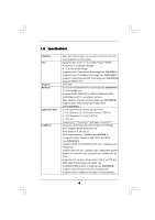
Processors in LGA1156 Package - 4 + 1 Power Phase Design - Supports Intel® Turbo Boost Technology (see CAUTION 1) - Supports Hyper-Threading Technology (see CAUTION 2) - Supports Untied Overclocking Technology (see CAUTION 3) - Supports EM64T CPU - Intel® H55 - Dual Channel DDR3 Memory Technology - ASRock H55M | User Manual - Page 7
Audio LAN Rear Panel I/O Connector BIOS Feature - 7.1 CH HD Audio (VIA® VT1718S Audio Codec) - PCIE x1 Gigabit LAN 10/100/1000 Mb/s - Realtek RTL8111DL - Supports Wake-On-LAN I/O Panel - 1 x PS/2 Keyboard Port - 1 x VGA/D-Sub Port - 1 x VGA/DVI-D Port - 1 x HDMI Port - 1 x Optical SPDIF Out Port - - ASRock H55M | User Manual - Page 8
Support CD - Drivers, Utilities, AntiVirus Software (Trial Version), ASRock Software Suite (CyberLink DVD Suite and Creative Sound Blaster X-Fi MB) (OEM and Trial Version) Unique Feature - ASRock OC Tuner (see CAUTION 13) - Intelligent Energy Saver (see CAUTION 14) - Instant Boot - ASRock BIOS - ASRock H55M | User Manual - Page 9
motherboard supports Dual Channel Memory Technology. Before you implement Dual Channel Memory Technology, make sure to read the installation guide only support up to DDR3 1333, the XMP DDR3 1600 is supported through overclocking 13. It is a user-friendly ASRock overclocking tool which allows you to - ASRock H55M | User Manual - Page 10
embedded in Flash ROM. This convenient BIOS update tool allows you to update system BIOS without entering operating systems first like MS-DOS or Windows®. With this utility, you can press key during the POST or press key to BIOS setup menu to access ASRock Instant Flash. Just launch this - ASRock H55M | User Manual - Page 11
Card Support List (for Windows® XP / XP 64-bit / VistaTM / VistaTM 64-bit) Chipset Vendor ATI Model Name Chipset Name Driver ASUS-EAH4350 updates of the supported PCI Express VGA card list for CrossFireXTM Mode, please visit our website for details. ASRock website: http://www.asrock.com/support - ASRock H55M | User Manual - Page 12
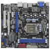
Motherboard ) eSATAII1/USB2 HDMI1 eSATAII2/USB3 Gigabit LAN 31 30 29 H55M PCI Express 2.0 PCIE1 DDR3 2600+ SATAII_4 AUDIO CODEC Super I/O PCIE2 PCIE3 COM1 1 PCI1 LPT1 1 CMOS Battery Intel H55 IR1 1 16Mb BIOS 1156-Pin CPU Socket 21 Chassis Intrusion Header (CI1) 6 2 x 240-pin DDR3 - ASRock H55M | User Manual - Page 13
1.5 I/O Panel 1 2 3 47 58 69 14 13 12 11 10 1 USB 2.0 Ports (USB45) 2 VGA/D-Sub Port * 3 LAN RJ-45 Port 4 Central / Bass (Orange) 5 Rear Speaker (Black) 6 Optical SPDIF Out Port 7 Line In (Light Blue) ** 8 Front Speaker (Lime) 9 Microphone (Pink) 10 USB 2.0 Ports (USB01) 11 Powered eSATAII - ASRock H55M | User Manual - Page 14
cable to the front panel audio header. After restarting your computer, you will find "VIA HD Audio Deck" tool on your system. Please follow below instructions according to the OS you install. For Windows® XP / XP 64-bit OS: Please click "VIA HD Audio Deck" icon. Click "Jack" and then click - ASRock H55M | User Manual - Page 15
settings. 1. Unplug the power cord from the wall socket before touching any component. 2. To avoid damaging the motherboard components due to static electricity, NEVER place your motherboard directly on the carpet or the like. Also remember to use a grounded wrist strap or touch a safety grounded - ASRock H55M | User Manual - Page 16
please follow the steps below. Load Plate Load Lever Contact Array Socket Body 1156-Pin Socket Overview Before you insert the 1156-Pin CPU into the socket, please check if the CPU surface is unclean off the PnP cap. 2. This cap must be placed if returning the motherboard for after service. 16 - ASRock H55M | User Manual - Page 17
Heat Sink) up. Locate Pin1 and the two orientation key notches. orientation key notch alignment key Pin1 Pin1 orientation key notch 1156-Pin CPU alignment key 1156-Pin Socket For proper inserting, please ensure to match the two orientation key notches of the CPU with the two alignment keys - ASRock H55M | User Manual - Page 18
refer to the instruction manuals of your CPU fan and heatsink. Below is an example to illustrate the installation of the heatsink for 1156-Pin CPU. or contact other components. Please be noticed that this motherboard supports Combo Cooler Option (C.C.O.), which provides the flexible option to - ASRock H55M | User Manual - Page 19
Memory Modules (DIMM) H55M motherboard provides two 240-pin DDR3 (Double Data Rate 3) DIMM slots, and supports Dual Channel Memory Technology. For dual channel configuration, you always need to install two identical (the same brand, speed, size and chiptype) memory modules in the DDR3 DIMM slots to - ASRock H55M | User Manual - Page 20
lane width graphics cards, or used to install PCI Express graphics cards to support CrossFireXTM function. PCIE2 (PCIE x1 slot; White) is used for PCI the installation. Step 2. Remove the system unit cover (if your motherboard is already installed in a chassis). Step 3. Remove the bracket facing - ASRock H55M | User Manual - Page 21
Guide This motherboard supports supported with Windows® XP with Service Pack 2 / VistaTM / 7 OS. Quad CrossFireXTM feature are supported with Windows® VistaTM / 7 OS only. Please check AMD website for ATITM CrossFireXTM driver updates graphics card manuals for detailed installation guide. Step 1. - ASRock H55M | User Manual - Page 22
Bridge Interconnects on the top of Radeon graphics cards. (CrossFire Bridge is provided with the graphics card you purchase, not bundled with this motherboard. Please refer to your graphics card vendor for details.) CrossFire Bridge or Step 2. Connect the DVI monitor cable to the DVI connector - ASRock H55M | User Manual - Page 23
utility to uninstall any previously installed Catalyst drivers prior to installation. Please check AMD website for ATITM driver updates. Step 3. Step 4. Step 5. Install the required drivers to your system. For Windows® XP OS: A. ATITM recommends Windows® XP Service Pack 2 or higher to be installed - ASRock H55M | User Manual - Page 24
for identification or explanation and to the owners' benefit, without intent to infringe. * For further information of ATITM CrossFireXTM technology, please check AMD website for updates and details. 24 - ASRock H55M | User Manual - Page 25
Display Feature This motherboard supports Surround Display upgrade. With the external add-on PCI Express VGA cards, you can easily enjoy the benefits of Surround Display feature. For the detailed instruction, please refer to the document at the following path in the Support CD: ..\ Surround Display - ASRock H55M | User Manual - Page 26
P+8 P-8 USB_PWR USB_PWR P-7 P+7 GND DUMMY Besides four default USB 2.0 ports on the I/O panel, there are three USB 2.0 headers on this motherboard. Each USB 2.0 header can support two USB 2.0 ports. Print Port Header (25-pin LPT1) (see p.12 No. 24) 1 GND P+6 P-6 USB_PWR AFD# ERROR# PINIT# SLIN - ASRock H55M | User Manual - Page 27
supports an optional wireless transmitting and receiving infrared module. This motherboard supports supports Jack Sensing, but the panel wire on the chassis must support HDA to function correctly. Please follow the instruction in our manual and chassis manual panel. E. Enter BIOS Setup Utility. Enter - ASRock H55M | User Manual - Page 28
12 No. 3) 1 2 3 4 Please connect a CPU fan cable to this connector and match the black wire to the ground pin. Though this motherboard provides 4-Pin CPU fan (Quiet Fan) support, the 3-Pin CPU fan still can work successfully even without the fan speed control function. If you plan to connect the - ASRock H55M | User Manual - Page 29
#1 DDSR#1 CCTS#1 1 RRI#1 RRTS#1 GND TTXD1 DDCD#1 This COM1 header supports a serial port module. HDMI_SPDIF Header (3-pin HDMI_SPDIF1) (see p.12 No. 30 the black end (A) of HDMI_SPDIF cable to the HDMI_SPDIF header on the motherboard. Then connect the white end (B or C) of HDMI_SPDIF cable to the - ASRock H55M | User Manual - Page 30
motherboard with a HDMI_SPDIF header. This motherboard motherboard. For the proper installation of HDMI VGA card, please refer to the installation guide manual of HDMI VGA card vendor. Incorrect connection may cause permanent damage to this motherboard Otherwise, the motherboard and the user manual for - ASRock H55M | User Manual - Page 31
guide. Some default setting of SATAII hard disks may not be at SATAII mode, which operate with the best performance. In order to enable SATAII function, please follow the below instruction 's website for details: http://www.hitachigst.com/hdd/support/download.htm The above examples are just for your - ASRock H55M | User Manual - Page 32
(SATAII) Hard Disks Installation This motherboard adopts Intel® H55 bridge chipset that supports Serial ATA (SATA) / Serial ATAII (SATAII) hard disks. You may install SATA / SATAII hard disks on this motherboard for internal storage devices. This section will guide you to install the SATA / SATAII - ASRock H55M | User Manual - Page 33
is installed into system properly. The latest SATA / SATAII driver is available on our support website: www.asrock.com 4. Make sure to use the SATA power cable & data cable, which are from our motherboard package. 5. Please follow below instructions step by step to reduce the risk of HDD crash or - ASRock H55M | User Manual - Page 34
cable to (White) to the power supply 1x4-pin cable. the motherboard's SATAII connector. SATA power cable 1x4-pin power connector (White) Step attention, before you process the Hot Unplug: Please do follow below instruction sequence to process the Hot Unplug, improper procedure will cause the SATA - ASRock H55M | User Manual - Page 35
Driver Installation Guide To install the drivers to your system, please insert the support CD to your optical drive first. Then, the drivers compatible to your system can be auto-detected and listed on the support CD driver function STEP 1: Set Up BIOS. A. Enter BIOS SETUP UTILITY Advanced screen - ASRock H55M | User Manual - Page 36
Technology This motherboard supports Untied Overclocking Technology, which means during overclocking, FSB enjoys better margin due to fixed PCI / PCIE buses. Before you enable Untied Overclocking function, please enter "Overclock Mode" option of BIOS setup to set the selection from [Auto] to [Manual - ASRock H55M | User Manual - Page 37
the BIOS SETUP UTILITY to configure your system. The BIOS FWH chip on the motherboard stores the BIOS SETUP UTILITY. You may run the BIOS SETUP off and then back on. Because the BIOS software is constantly being updated, the following BIOS setup screens and descriptions are for reference purpose - ASRock H55M | User Manual - Page 38
Overview System Time System Date [14:00:09] [Mon 11/09/2009] BIOS Version : H55M P1.00 Processor Type : Intel (R) Core (TM) CPU 870 @ 2.93GHz (64bit) Processor Speed : 2933MHz Microcode Update : 106E5/3 Cache Size : 8192KB Total Memory DDR3_A1 DDR3_B1 : 2048MB Single-Channel Memory - ASRock H55M | User Manual - Page 39
Setting [Disabled] Profile 1 : DDR3 2000 9-9-9-27 1.65V Intelligent Energy cause damage to your memory and motherboard. It should be done at your item to [Enabled]. Besides the BIOS option, you can also choose our Manual], [I.O.T.] and [Optimized]. The default value is [Auto]. If you select [Manual - ASRock H55M | User Manual - Page 40
ratio value of this motherboard. DRAM Frequency If [Auto] is selected, the motherboard will detect the memory module DRAM tRCD DRAM tRP DRAM tRAS DRAM tRFC DRAM tWR DRAM tWTR DRAM tRRD DRAM tRTP DRAM tFAW DRAM Command Rate BIOS SETUP UTILITY 9 [Auto] 9 [Auto] 9 [Auto] 24 [Auto] 74 [Auto] 10 [Auto] - ASRock H55M | User Manual - Page 41
DRAM tRAS This controls the number of DRAM clocks for TRAS. Configuration options: [Auto], [9] to [31]. DRAM tRFC This controls the number of DRAM clocks for TRFC. Configuration options: [Auto], [15] to [255]. DRAM tWR This controls the number of DRAM clocks for TWR. Configuration options: [Auto], - ASRock H55M | User Manual - Page 42
VDrop Control Use this to enable or disable ASRock VDrop control. Configuration options: [With VDrop] and [Without VDrop]. The default value is [With VDrop]. CPU Voltage Use this to select CPU Voltage. Configuration options: [Auto], [Manual] and [Overdrive Offset]. The default value is [Auto]. DRAM - ASRock H55M | User Manual - Page 43
Setting wrong values in this section may cause the system to malfunction. ASRock Instant Flash ASRock Instant Flash is a BIOS flash utility embedded in Flash ROM. This convenient BIOS update tool allows you to update system BIOS without entering operating systems first like MS-DOS or Windows®. Just - ASRock H55M | User Manual - Page 44
3.4.1CPU Configuration BIOS SETUP UTILITY Advanced Configure advanded CPU settings Intel (R) Core ( this motherboard. Enhance Halt State All processors support the Halt State (C1). The C1 state is supported through the native processor instructions HLT and MWAIT and requires no hardware support - ASRock H55M | User Manual - Page 45
® VistaTM and want to enable this function, please set this item to [Enabled]. This item will be hidden if the current CPU does not support Intel (R) SpeedStep(tm) tech.. Please note that enabling this function may reduce CPU voltage and lead to system stability or compatibility issue with some - ASRock H55M | User Manual - Page 46
3.4.2Chipset Configuration BIOS SETUP UTILITY Advanced Chipset Settings Primary Graphics Adapter architecture that offers breakthrough performance for the motherboard through efficient memory utilization. In DVMT mode, the graphics driver allocates memory as needed for running graphics - ASRock H55M | User Manual - Page 47
OnBoard Lan This allows you to enable or disable the "OnBoard Lan" feature. Intel VT-d Configuration Use this to enable or disable Intel® VT-d technology (Intel® Virtualization Technology for Directed I/O). The default value of this feature is [Disabled]. 47 - ASRock H55M | User Manual - Page 48
3.4.3 ACPI Configuration BIOS SETUP UTILITY Advanced ACPI disable the Suspend-toRAM feature. Select [Auto] will enable this feature if the OS supports it. If you set this item to [Disabled], the function "Repost Video on STR plan to use this motherboard to submit Windows® VistaTM certification. 48 - ASRock H55M | User Manual - Page 49
3.4.4 Storage Configuration BIOS SETUP UTILITY Advanced Storage Configuration SATA Operation Mode SATAII 1,2,3,4 Plug" and "Link Power Management" will appear. AHCI (Advanced Host Controller Interface) supports NCQ and other new features that will improve SATA disk performance but IDE mode does - ASRock H55M | User Manual - Page 50
" as the example in the following instruction. BIOS SETUP UTILITY Advanced Primary IDE Master Device :ST340014A :40.0 GB :Supported :16Sectors :4 :MultiWord DMA-2 :Ultra DMA-5 :Supported [Auto] [Auto] [Auto the LBA/Large mode for a hard disk > 512 MB under DOS and Windows; for Netware and UNIX user, - ASRock H55M | User Manual - Page 51
Enabled]. 32-Bit Data Transfer Use this item to enable 32-bit access to maximize the IDE hard disk data transfer rate. 3.4.5PCIPnP Configuration BIOS SETUP UTILITY Advanced Advanced PCI / PnP Settings PCI Latency Timer PCI IDE BusMaster [64] [Enabled] Value in units of PCI clocks for PCI device - ASRock H55M | User Manual - Page 52
3.4.6 Super IO Configuration BIOS SETUP UTILITY Advanced Configure Super IO Chipset Serial Port Address Infrared Port Address Parallel Port Address Parallel Port Mode EPP Version ECP Mode DMA Channel - ASRock H55M | User Manual - Page 53
Use this item to enable or disable the use of USB controller. Legacy USB Support Use this option to select legacy support for USB devices. There are four configuration options: [Enabled], [Auto], [Disabled] and [BIOS Setup Only]. The default value is [Enabled]. Please refer to below descriptions for - ASRock H55M | User Manual - Page 54
of the CPU temperature, motherboard temperature, CPU fan speed, chassis fan speed, and the critical voltage. BIOS SETUP UTILITY Main OC allows you to set the chassis fan speed. Configuration options: [Full On] and [Manual mode]. The default is value [Full On]. Case Open Feature This allows you to - ASRock H55M | User Manual - Page 55
F1 General Help F9 Load Defaults F10 Save and Exit ESC Exit v02.54 (C) Copyright 1985-2005, American Megatrends, Inc. 3.6.1 Boot Settings Configuration BIOS SETUP UTILITY Boot Boot Settings Configuration Full Screen Logo AddOn ROM Display Boot Logo Boot From Onboard LAN Bootup Num-Lock [Enabled - ASRock H55M | User Manual - Page 56
option "Full Screen Logo". Configuration options: [Auto], [EuP], [Scenery] and [ASRock]. The default value is [Auto]. Boot From Onboard LAN Use this item to enable system. For the user password, you may also clear it. BIOS SETUP UTILITY Main OC Tweaker Advanced H/W Monitor Boot Security Exit - ASRock H55M | User Manual - Page 57
. Discard Changes When you select this option, it will pop-out the following message, "Discard changes?" Select [OK] to discard all changes. Load BIOS Defaults Load BIOS default values for all the setup questions. F9 key can be used for this operation. Load Performance Setup Default (IDE/SATA) This - ASRock H55M | User Manual - Page 58
install the necessary drivers to activate the devices. 4.2.3 Utilities Menu The Utilities Menu shows the applications software that the motherboard supports. Click on a specific item then follow the installation wizard to install it. 4.2.4 Contact Information If you need to contact ASRock or want to
-
 1
1 -
 2
2 -
 3
3 -
 4
4 -
 5
5 -
 6
6 -
 7
7 -
8
-
9
-
10
-
11
-
12
-
13
-
14
-
15
-
16
-
17
-
18
-
19
-
20
-
21
-
22
-
23
-
24
-
25
-
26
-
27
-
28
-
29
-
30
-
31
-
32
-
33
-
34
-
35
-
36
-
37
-
38
-
39
-
40
-
41
-
42
-
43
-
44
-
45
-
46
-
47
-
48
-
49
-
50
-
51
-
52
-
53
-
54
-
55
-
56
-
57
-
58
 |
 |

1
H55M
User Manual
Version 1.
1
Published
March
20
10
Copyright©20
10
ASRock INC. All rights reserved.