ASRock H610M-ITX/eDP User Manual
ASRock H610M-ITX/eDP Manual
 |
View all ASRock H610M-ITX/eDP manuals
Add to My Manuals
Save this manual to your list of manuals |
ASRock H610M-ITX/eDP manual content summary:
- ASRock H610M-ITX/eDP | User Manual - Page 1
- ASRock H610M-ITX/eDP | User Manual - Page 2
without notice, and should not be constructed as a commitment by ASRock. ASRock assumes no responsibility for any errors or omissions that may appear energy and, if not installed and used in accordance with the instructions, may cause harmful interference to radio communications. However, there is - ASRock H610M-ITX/eDP | User Manual - Page 3
of which may be identified in, and licensed in accordance with, an enclosed license.txt file or other text or file. (e) Intel has no obligation to provide any support, technical assistance or updates for the Software. OWNERSHIP OF SOFTWARE AND COPYRIGHTS. Title to all copies of the Software remains - ASRock H610M-ITX/eDP | User Manual - Page 4
if Licensee is in breach of any of its terms or conditions. Upon termination, Licensee will immediately destroy or return to Intel all copies of the Software. THIRD PARTY BENEFICIARY. Intel is an intended beneficiary of the End User License Agreement and has the right to enforce all of its terms - ASRock H610M-ITX/eDP | User Manual - Page 5
the essential requirements and other relevant provisions of related Directives. Full text of EU declaration of conformity is available at: http://www.asrock.com ASRock follows the green design concept to design and manufacture our products, and makes sure that each stage of the product life cycle - ASRock H610M-ITX/eDP | User Manual - Page 6
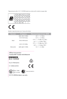
Operations in the 5.15-5.35GHz band are restricted to indoor usage only. Radio transmit power per transceiver type Function WiFi Bluetooth Frequency 2400-2483.5 MHz 5150-5250 MHz 5250-5350 MHz 5470-5725 MHz 2400-2483.5 MHz Maximum Output Power (EIRP) 18.5 + / -1.5 dbm 21.5 + / -1.5 dbm 18.5 + / - ASRock H610M-ITX/eDP | User Manual - Page 7
21 2.7 M.2_SSD (NGFF) Module Installation Guide (M2_1) 25 2.8 Change Screen Brightness for eDP in Windows® 29 Chapter 3 Software and Utilities Operation 31 3.1 Installing Drivers 31 3.2 ASRock Motherboard Utility (A-Tuning) 32 3.2.1 Installing ASRock Motherboard Utility (A-Tuning) 32 - ASRock H610M-ITX/eDP | User Manual - Page 8
3.3.1 UI Overview 35 3.3.2 Apps 36 3.3.3 BIOS & Drivers 39 3.3.4 Setting 40 Chapter 4 UEFI SETUP UTILITY 41 4.1 Introduction 41 4.2 EZ Mode 42 4.3 Advanced Mode 43 4.3.1 UEFI Menu Bar 43 4.3.2 Navigation Keys 44 4.4 Main Screen 45 4.5 OC Tweaker Screen 46 4.6 Advanced Screen - ASRock H610M-ITX/eDP | User Manual - Page 9
the latest VGA cards and CPU support list on ASRock's website as well. ASRock website http://www.asrock.com. 1.1 Package Contents • ASRock H610M-ITX/eDP Motherboard (Mini-ITX Form Factor) • ASRock H610M-ITX/eDP Quick Installation Guide • ASRock H610M-ITX/eDP Support CD • 2 x Serial ATA (SATA) Data - ASRock H610M-ITX/eDP | User Manual - Page 10
memory up to 3200* * Please refer to Memory Support List on ASRock's website for more information. (http://www.asrock.com/) • Supports ECC UDIMM memory modules (operate in non- ECC mode) • Max. capacity of system memory: 64GB • Supports Intel® Extreme Memory Profile (XMP) 2.0 Expansion Slot CPU - ASRock H610M-ITX/eDP | User Manual - Page 11
H610M-ITX/eDP • Supports Triple Monitor • Supports eDP 1.4 with max. resolution up to Full HD (1920x1080) @ 60Hz • Supports HDMI 2.1 TMDS Compatible with max. resolution up to 4K x 2K (4096x2160) @ 60Hz • Supports DisplayPort 1.4 with DSC (compressed) max. resolution up to 8K (7680x4320) @ 60Hz / - ASRock H610M-ITX/eDP | User Manual - Page 12
Gb/s & PCIe Gen3x4 (32 Gb/s) modes* • 4 x SATA3 6.0 Gb/s Connectors** * Supports NVMe SSD as boot disks * Supports ASRock U.2 Kit ** If M2_1 is occupied by a SATA-type M.2 device, SATA3_0 will be disabled. Connector • 1 x eDP Signal Connector • 1 x CPU Fan Connector (4-pin) * The CPU Fan Connector - ASRock H610M-ITX/eDP | User Manual - Page 13
H610M-ITX/eDP Hardware Monitor OS Certifications • Fan Tachometer: CPU, Chassis, Chassis/Water supply is required) * For detailed product information, please visit our website: http://www.asrock.com Please realize that there is a certain risk involved with overclocking, including adjusting the - ASRock H610M-ITX/eDP | User Manual - Page 14
1.3 Motherboard Layout Top Side View 6 English - ASRock H610M-ITX/eDP | User Manual - Page 15
Back Side View H610M-ITX/eDP English 7 - ASRock H610M-ITX/eDP | User Manual - Page 16
SATA3 Connector (SATA3_3) 13 System Panel Header (PANEL1) 14 Clear CMOS Jumper (CLRMOS1) 15 Chassis Speaker Header (SPEAKER1) 16 Front Panel Audio Header (HD_AUDIO1) 17 eDP Signal Connector (EDP1) 8 English - ASRock H610M-ITX/eDP | User Manual - Page 17
1.4 I/O Panel H610M-ITX/eDP 2 1 3 9 8 No. Description 1 LAN RJ-45 Port* 2 Line In (Light Blue)** 3 Front Speaker (Lime)** 4 Microphone (Pink)** 5 Antenna Ports 7 6 5 4 No. Description 6 USB 3.2 Gen1 Ports (USB32_12) 7 USB 2.0 Ports ( - ASRock H610M-ITX/eDP | User Manual - Page 18
1.5 WiFi-802.11ac Module and ASRock WiFi 2.4/5 GHz Antennas WiFi-802.11ac + BT Module This motherboard comes with an exclusive WiFi 802.11 a/b/g/n/ac + BT v5.1 module (pre-installed on the rear I/O panel) that offers support for WiFi 802.11 a/b/ g/n/ac connectivity standards and Bluetooth v5.1. - ASRock H610M-ITX/eDP | User Manual - Page 19
H610M-ITX/eDP WiFi Antennas Installation Guide Step 1 Prepare the WiFi 2.4/5 GHz Antennas that come with the package. Step 2 Connect the two WiFi 2.4/5 GHz Antennas to the antenna connectors. Turn the antenna - ASRock H610M-ITX/eDP | User Manual - Page 20
Chapter 2 Installation This is a Mini-ITX form factor motherboard. Before you install the motherboard, study the configuration of your chassis to ensure that the motherboard fits into it. Pre-installation Precautions - ASRock H610M-ITX/eDP | User Manual - Page 21
H610M-ITX/eDP 2.1 Installing the CPU 1. Before you insert the 1700-Pin CPU into the socket, please check if the PnP cap is on the socket, if the - ASRock H610M-ITX/eDP | User Manual - Page 22
5 7 6 4 14 English - ASRock H610M-ITX/eDP | User Manual - Page 23
H610M-ITX/eDP Please save and replace the cover if the processor is removed. The cover must be placed if you wish to return the motherboard for after service. 15 English - ASRock H610M-ITX/eDP | User Manual - Page 24
2.2 Installing the CPU Fan and Heatsink 1 16 2 CPU_FAN English - ASRock H610M-ITX/eDP | User Manual - Page 25
H610M-ITX/eDP 2.3 Installing Memory Modules (DIMM) This motherboard provides two 288-pin DDR4 (Double Data Rate 4) DIMM slots, and supports Dual Channel Memory Technology. 1. For dual channel configuration, you always need to install identical (the same brand, speed, size and chip-type) DDR4 DIMM - ASRock H610M-ITX/eDP | User Manual - Page 26
1 2 3 18 English - ASRock H610M-ITX/eDP | User Manual - Page 27
H610M-ITX/eDP 2.4 Expansion Slots (PCIe Slot) There is 1 PCIe slot on the motherboard. Before installing an expansion card, please make sure that the power supply is switched - ASRock H610M-ITX/eDP | User Manual - Page 28
2.5 Jumpers Setup The illustration shows how jumpers are setup. When the jumper cap is placed on the pins, the jumper is "Short". If no jumper cap is placed on the pins, the jumper is "Open". Clear CMOS Jumper (CLRMOS1) (see p.6, No. 14) 2-pin Jumper CLRMOS1 allows you to clear the data in CMOS. - ASRock H610M-ITX/eDP | User Manual - Page 29
H610M-ITX/eDP 2.6 Onboard Headers and Connectors Onboard headers and connectors are NOT jumpers. Do NOT place jumper caps over these headers and connectors. Placing jumper caps over - ASRock H610M-ITX/eDP | User Manual - Page 30
see p.6, No. 12) SATA3_3 SATA3_1 SATA3_2 SATA3_0 These four SATA3 connectors support SATA data cables for internal storage devices with up to 6.0 Gb/s data support HDA to function correctly. Please follow the instructions in our manual and chassis manual to install your system. 2. If you use an AC - ASRock H610M-ITX/eDP | User Manual - Page 31
H610M-ITX/eDP Chassis Speaker Header (4-pin SPEAKER1) (see p.6, No. 15) SPEAKER DUMMY DUMMY +5V 1 Please connect the chassis speaker to this header. Chassis/Water Pump Fan Connector (4- - ASRock H610M-ITX/eDP | User Manual - Page 32
English ATX 12V Power Connector (8-pin ATX12V1) (see p.6, No. 2) eDP Signal Connector (40-pin EDP1) (see p.7, No. 17) 24 8 5 4 1 PIN SIGNAL 1 an LCD monitor that supports an internal embedded DisplayPort (eDP). *Please refer to page 29 for further instructions on how to adjust the brightness. - ASRock H610M-ITX/eDP | User Manual - Page 33
H610M-ITX/eDP 2.7 M.2_SSD (NGFF) Module Installation Guide (M2_1) The M.2, also known as the Next Generation Form Factor (NGFF), is a small size and versatile card edge connector that aims to replace mPCIe and mSATA. The Ultra M.2 Socket (M2_1, Key M), supports type 2280 SATA3 6.0 Gb/s & PCIe Gen3x4 - ASRock H610M-ITX/eDP | User Manual - Page 34
Step 3 Align and gently insert the M.2 (NGFF) SSD module into the M.2 slot. Please be aware that the M.2 (NGFF) SSD module only fits in one orientation. A A 20o NUT2 NUT1 Step 4 Tighten the screw with a screwdriver to secure the module into place. Please do not overtighten the screw as this - ASRock H610M-ITX/eDP | User Manual - Page 35
Module Support List Vendor ADATA ADATA ADATA ADATA ADATA ADATA ADATA ADATA ADATA ADATA Apacer Corsair Crucial Crucial Intel Intel Intel Kingston (NVME) XP941-512G (MZHPU512HCGL) SD6PP4M-128G SD6PP4M-256G TM4PS4128GMC105 TM4PS4256GMC105 TM8PS4128GMC105 TM8PS4256GMC105 H610M-ITX/eDP 27 English - ASRock H610M-ITX/eDP | User Manual - Page 36
VSM100-240G-2280 VLM100-240G-2280B-RD WDS100T1B0B-00AS40 WDS240G1G0B-00RC30 WDS256G1X0C-00ENX0 (NVME) WDS512G1X0C-00ENX0 (NVME) For the latest updates of M.2_SSD (NFGG) module support list, please visit our website for details: http://www.asrock.com English 28 - ASRock H610M-ITX/eDP | User Manual - Page 37
H610M-ITX/eDP 2.8 Change Screen Brightness for eDP in Windows® This section explains how to change screen brightness in Windows® when you use an eDP panel. The following is a setup example for Windows® 11. Setup procedures may vary from different operating systems. Setup Guide Step 1 Right click on - ASRock H610M-ITX/eDP | User Manual - Page 38
Step 3 You might also see another check box displayed: Help improve battery by optimizing the content shown and brightness. Select the check box to turn on the content adaptive brightness control if needed. 30 English - ASRock H610M-ITX/eDP | User Manual - Page 39
H610M-ITX/eDP Chapter 3 Software and Utilities Operation 3.1 Installing Drivers The Support CD that comes with the motherboard contains necessary drivers and useful utilities that enhance the motherboard's features. Running The Support CD To begin using the support CD, insert the CD into your CD-ROM - ASRock H610M-ITX/eDP | User Manual - Page 40
more new features and improved utilities. 3.2.1 Installing ASRock Motherboard Utility (A-Tuning) ASRock Motherboard Utility (A-Tuning) can be downloaded from ASRock Live Update & APP Shop. After the installation, you will find the icon "ASRock Motherboard Utility (A-Tuning)" on your desktop. Double - ASRock H610M-ITX/eDP | User Manual - Page 41
OC Tweaker Configurations for overclocking the system. H610M-ITX/eDP System Info View information about the system. *The System Browser tab may not appear for certain models. 33 English - ASRock H610M-ITX/eDP | User Manual - Page 42
shift to the next speed level when the assigned temperature is met. Settings Configure ASRock ASRock Motherboard Utility (A-Tuning). Click to select "Auto run at Windows Startup" if you want ASRock Motherboard Utility (A-Tuning) to be launched when you start up the Windows operating system - ASRock H610M-ITX/eDP | User Manual - Page 43
H610M-ITX/eDP 3.3 ASRock Live Update & APP Shop The ASRock Live Update & APP Shop is an online store for purchasing and downloading software applications for your ASRock computer. You can quickly and easily install various apps and support utilities. With ASRock Live Update & APP Shop, you can - ASRock H610M-ITX/eDP | User Manual - Page 44
3.3.2 Apps When the "Apps" tab is selected, you will see all the available apps on screen for you to download. Installing an App Step 1 Find the app you want to install. The most recommended app appears on the left side of the screen. The other various apps are shown on the right. Please scroll up - ASRock H610M-ITX/eDP | User Manual - Page 45
H610M-ITX/eDP Step 3 If you want to install the app, click on the red icon to start downloading. Step 4 When installation completes, you can find the green " - ASRock H610M-ITX/eDP | User Manual - Page 46
Upgrading an App You can only upgrade the apps you have already installed. When there is an available new version for your app, you will find the mark of "New Version" appears below the installed app icon. Step 1 Click on the app icon to see more details. Step 2 Click on the yellow icon to start - ASRock H610M-ITX/eDP | User Manual - Page 47
H610M-ITX/eDP 3.3.3 BIOS & Drivers Installing BIOS or Drivers When the "BIOS & Drivers" tab is selected, you will see a list of recommended or critical updates for the BIOS - ASRock H610M-ITX/eDP | User Manual - Page 48
3.3.4 Setting In the "Setting" page, you can change the language, select the server location, and determine if you want to automatically run the ASRock Live Update & APP Shop on Windows startup. 40 English - ASRock H610M-ITX/eDP | User Manual - Page 49
H610M-ITX/eDP Chapter 4 UEFI SETUP UTILITY 4.1 Introduction This section explains how to use the UEFI SETUP UTILITY to configure your system. You may run the UEFI SETUP - ASRock H610M-ITX/eDP | User Manual - Page 50
4.2 EZ Mode The EZ Mode screen appears when you enter the BIOS setup program by default. EZ mode is a dashboard which contains multiple readings of the system's current status. You can check the most crucial information of your system, such as CPU speed, DRAM frequency, SATA information, fan speed, - ASRock H610M-ITX/eDP | User Manual - Page 51
H610M-ITX/eDP 4.3 Advanced Mode The Advanced Mode provides more options to configure the BIOS settings. Refer to the following sections for the detailed configurations. To access the - ASRock H610M-ITX/eDP | User Manual - Page 52
4.3.2 Navigation Keys Use < > key or < > key to choose among the selections on the menu bar, and use < > key or < > key to move the cursor up or down to select items, then press to get into the sub screen. You can also use the mouse to click your required item. Please check the following - ASRock H610M-ITX/eDP | User Manual - Page 53
H610M-ITX/eDP 4.4 Main Screen When you enter the UEFI SETUP UTILITY, the Main screen will appear and display the system overview. The availability and location of BIOS - ASRock H610M-ITX/eDP | User Manual - Page 54
4.5 OC Tweaker Screen In the OC Tweaker screen, you can set up overclocking features. Because the UEFI software is constantly being updated, the following UEFI setup screens and descriptions are for reference purpose only, and they may not exactly match what you see on your screen. CPU Vcore - ASRock H610M-ITX/eDP | User Manual - Page 55
H610M-ITX/eDP The CPU speed is determined by the CPU P-Core Ratio multiplied with the BCLK. Increasing the CPU P-Core Ratio will Overclock Mode Nominal is good for normal core ratio overclocking. Elevated and Extremely El¬evated are good for high BCLK OC. Intel SpeedStep Technology 47 English - ASRock H610M-ITX/eDP | User Manual - Page 56
service controls thermal based voltage optimizations for processors that implment the Intel Thermal Velocity Boost (TVB) feature. Dual Tau Boost Enable Dual Tau Boost feature. This is only applicable for CMLS 35W/65W/125W skus. This item is only supported exceeded. PSU Select Guide Adjust CPU Power - ASRock H610M-ITX/eDP | User Manual - Page 57
H610M-ITX/eDP DRAM Timing Configuration DRAM Reference Clock Select Auto for optimized settings. DRAM Frequency If [Auto] is selected, the motherboard will detect the memory module(s) inserted - ASRock H610M-ITX/eDP | User Manual - Page 58
DDR4 initiates a minimum of one refresh command internally once it enters Self-Refresh mode. tRC Use this item to change RAS# Cycle Time (tRC) Auto/Manual setting. 50 English - ASRock H610M-ITX/eDP | User Manual - Page 59
. tWRRD_sg Configure between module write to read delay. tWRRD_dg Configure between module write to read delay. tWRRD_dr Configure between module write to read delay. tWRRD_dd H610M-ITX/eDP 51 English - ASRock H610M-ITX/eDP | User Manual - Page 60
Configure between module write to read delay. tWRWR_sg Configure between module write to write delay. tWRWR_dg Configure between module write to write delay. tWRWR_dr Configure between module write to write delay. tWRWR_dd Configure between module write to write delay. TAT Runtime Value tRDRD_sg - ASRock H610M-ITX/eDP | User Manual - Page 61
Offset Configure round trip latency FIF0 delay initial offset. Initial RTL (MC0 C0 A1) Configure round trip latency initial value. Initial RTL (MC0 C1 A1) H610M-ITX/eDP 53 English - ASRock H610M-ITX/eDP | User Manual - Page 62
Configure round trip latency initial value. Initial RTL (MC1 C0 B1) Configure round trip latency initial value. Initial RTL (MC1 C1 B1) Configure round trip latency initial value. RTL (MC0 C0 A1) Configure round trip latency value. RTL (MC0 C1 A1) Configure round trip latency value. RTL (MC1 C0 B1) - ASRock H610M-ITX/eDP | User Manual - Page 63
H610M-ITX/eDP Configure the memory on die termination resistors' PARK for channel B1. Advanced Setting ASRock Timing Optimization Configure the fast path through the MRC. ASRock Second Timing Optimization Configure the second fast path through the MRC. MRC Training Respond Time Try Slowest MRC - ASRock H610M-ITX/eDP | User Manual - Page 64
Allows users to set VID Step as 5mV or 10mV. DRAM Voltage Use this to configure DRAM Voltage. The default value is [Auto]. VCCIN AUX Voltage Configure the voltage for the VCCIN AUX. +1.8V PROC Voltage Configure the CPU voltage (1.8V). +1.05V PROC Voltage Configure the CPU voltage (1.05V). +0.82V PCH - ASRock H610M-ITX/eDP | User Manual - Page 65
H610M-ITX/eDP VF Configuration Scope Allows all cores VF curve or per-core VF curve configuration. Core Voltage Offset Specifies the offset voltage applied to the IA - ASRock H610M-ITX/eDP | User Manual - Page 66
Selects between adaptive and Override Voltage modes. In Override Mode the voltage selected will be applied over all operating frequencies. In Adaptive Mode the voltage is interpolated only in turbo mode. Uses Mailbox 0SR 0x150, cmd 0x10, 0x11. Extra Turbo Voltage Specifies the extra turbo voltage - ASRock H610M-ITX/eDP | User Manual - Page 67
H610M-ITX/eDP 4.6 Advanced Screen In this section, you may set the configurations for Auto] is selected, the resolution will be set to 1920 x 1080 if the monitor supports Full HD resolution. If the monitor does not support Full HD resolution, then the resolution will be set to 1024 x 768. When [ - ASRock H610M-ITX/eDP | User Manual - Page 68
This item displays the E-Core Information. Intel Hyper Threading Technology Intel Hyper Threading Technology allows multiple threads to run of E-Cores to enable in each processor package. CPU C States Support Enable CPU C States Support for power saving. It is recommended to keep C6 and C7 enabled - ASRock H610M-ITX/eDP | User Manual - Page 69
H610M-ITX/eDP CPU C6 State Support Enable C6 deep sleep state for lower power consumption. CPU C7 State Support Enable C7 deep sleep state for lower power consumption. Package C State Support Enable CPU, PCIe, Memory, Graphics C State Support for power saving. CFG Lock This item allows you to - ASRock H610M-ITX/eDP | User Manual - Page 70
) If system has Resizable BAR capable PCIe Devices, use this option to enable or disable Resizable BAR support (only of the system supports 64-bit PCI decoding). VT-d Intel® Virtualization Technology for Directed I/O helps your virtual machine monitor better utilize hardware by improving application - ASRock H610M-ITX/eDP | User Manual - Page 71
H610M-ITX/eDP Configure DMI Slot Link Speed. Auto mode is optimizing for overclocking. PCIE1 Link Speed Select the link speed for PCIE1. PCI Express Native Control Select Enable for enhanced PCI Express power saving in OS. PCIE ASPM Support This option enables/disables the ASPM support for all CPU - ASRock H610M-ITX/eDP | User Manual - Page 72
Select the power state after a power failure. If [Power Off] is selected, the power will remain off when the power recovers. If [Power On] is selected, the system will start to boot up when the power recovers. 64 English - ASRock H610M-ITX/eDP | User Manual - Page 73
4.6.3 Storage Configuration H610M-ITX/eDP SATA Controller(s) Enable/disable the SATA controllers. SATA Mode Selection AHCI: Supports new features that improve performance. Hybrid Storage Detection and Configuration Mode This item allows you select Hybrid Storage Detection and Configuration Mode. - ASRock H610M-ITX/eDP | User Manual - Page 74
be waked up by a PCIE device and enable wake on LAN. I219 LAN Power On Allow the system to be waked up by the Onboard Intel LAN. RTC Alarm Power On Allow the system to be waked up by the real time clock alarm. Set it to By OS to let - ASRock H610M-ITX/eDP | User Manual - Page 75
4.6.5 USB Configuration H610M-ITX/eDP XHCI Hand-off This is a workaround for OSes without XHCI hand-off support. The XHCI ownership change should be claimed by XHCI driver. English 67 - ASRock H610M-ITX/eDP | User Manual - Page 76
4.6.6 Trusted Computing NOTE: Options vary depending on the version of your connected TPM module. Security Device Support Use this item to enable or disable BIOS support for security device. O.S. will not show Security Device. TCG EFI protocol and INT1A interface will not be available. Active PCR - ASRock H610M-ITX/eDP | User Manual - Page 77
H610M-ITX/eDP NOTE: Your computer will reboot during restart in order to change Use this item to select the TPM device to be supported. TPM 1.2 will restrict support to TPM 1.2 devices. TPM 2.0 will restrict support to TPM 2.0 devices. Auto will support both with the default set to TPM 2.0 devices. - ASRock H610M-ITX/eDP | User Manual - Page 78
4.7 Tools UEFI Tech Service Contact ASRock Tech Service if you are having trouble with your PC. Please setup network configuration before using UEFI Tech Service. SSD Secure Erase Tool All the SSD's listed that supports Secure Erase function. NVME Sanitization Tool After you Sanitize SSD, all user - ASRock H610M-ITX/eDP | User Manual - Page 79
Network Configuration Use this to configure internet connection settings for Internet Flash. H610M-ITX/eDP Internet Setting Enable or disable sound effects in the setup utility. UEFI Download Server Select a server to download the UEFI firmware. English 71 - ASRock H610M-ITX/eDP | User Manual - Page 80
4.8 Hardware Health Event Monitoring Screen This section allows you to monitor the status of the hardware on your system, including the parameters of the CPU temperature, motherboard temperature, fan speed and voltage. Fan Tuning Measure Fan Min Duty Cycle. Fan-Tastic Tuning Select a fan mode for - ASRock H610M-ITX/eDP | User Manual - Page 81
H610M-ITX/eDP Chassis Fan 1 Control Mode Select PWM mode or DC mode for Chassis Fan 1. Chassis Fan 1 Setting Select a fan mode for Chassis Fan 1, or choose Customize - ASRock H610M-ITX/eDP | User Manual - Page 82
settings in the UEFI Setup Utility. Leave it blank and press enter to remove the password. Secure Boot Use this item to enable or disable support for Secure Boot. Intel(R) Platform Trust Technology Enable/disable Intel PTT in ME. Disable this option to use discrete TPM Module. 74 English - ASRock H610M-ITX/eDP | User Manual - Page 83
H610M-ITX/eDP 4.10 Boot Screen This section displays the available devices on your system for you to configure the boot settings and the boot priority. Fast Boot Fast Boot minimizes your computer's boot time. In fast mode you may not boot from an USB storage device. The VBIOS must support UEFI GOP - ASRock H610M-ITX/eDP | User Manual - Page 84
If the computer fails to boot for a number of times the system automatically restores the default settings. CSM (Compatibility Support Module) CSM Enable to launch the Compatibility Support Module. Please do not disable unless you're running a WHCK test. Launch PXE OpROM Policy Select UEFI only to - ASRock H610M-ITX/eDP | User Manual - Page 85
H610M-ITX/eDP only to run those that support legacy option ROM only. Select Do not launch to not execute both legacy and UEFI option ROM. Other PCI Device ROM Priority For PCI devices other than Network. Mass storage or Video defines which OpROM to launch. 77 English - ASRock H610M-ITX/eDP | User Manual - Page 86
4.11 Exit Screen Save Changes and Exit When you select this option the following message, "Save configuration changes and exit setup?" will pop out. Select [OK] to save changes and exit the UEFI SETUP UTILITY. Discard Changes and Exit When you select this option the following message, "Discard - ASRock H610M-ITX/eDP | User Manual - Page 87
; or you may contact your dealer for further information. For technical questions, please submit a support request form at https://event.asrock.com/tsd.asp ASRock Incorporation e-mail: [email protected] ASRock EUROPE B.V. e-mail: [email protected] ASRock America, Inc. e-mail: [email protected]
-
 1
1 -
 2
2 -
 3
3 -
 4
4 -
 5
5 -
 6
6 -
 7
7 -
8
-
9
-
10
-
11
-
12
-
13
-
14
-
15
-
16
-
17
-
18
-
19
-
20
-
21
-
22
-
23
-
24
-
25
-
26
-
27
-
28
-
29
-
30
-
31
-
32
-
33
-
34
-
35
-
36
-
37
-
38
-
39
-
40
-
41
-
42
-
43
-
44
-
45
-
46
-
47
-
48
-
49
-
50
-
51
-
52
-
53
-
54
-
55
-
56
-
57
-
58
-
59
-
60
-
61
-
62
-
63
-
64
-
65
-
66
-
67
-
68
-
69
-
70
-
71
-
72
-
73
-
74
-
75
-
76
-
77
-
78
-
79
-
80
-
81
-
82
-
83
-
84
-
85
-
86
-
87
 |
 |