ASRock H61M-GS User Manual - Page 11
Intel - intel h61
 |
View all ASRock H61M-GS manuals
Add to My Manuals
Save this manual to your list of manuals |
Page 11 highlights
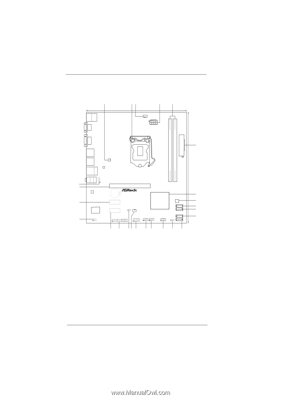
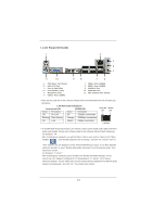
1.3 Motherboard Layout (H61M-GS / H61M-S) PS2 Mouse PS2 Keyboard 1 23 4 5 19.8cm (7.8 in) Designed in Taipei ErP/EuP Ready CPU_FAN1 ATX12V1 DX10.1 VGA1 24.4cm (9.6 in) DDR3 ATXPWR1 DDR3_B1 (64 bit, 240-pin module) DDR3_A1 (64 bit, 240-pin module) DVI1 25 24 23 22 Top: LINE IN Center: FRONT Bottom: MIC IN USB 2.0 T: USB0 B: USB1 PWR_FAN1 USB 2.0 T: USB2 B: USB3 LAN PHY USB 2.0 T: USB4 Top: B: USB5 RJ-45 AUDIO CODEC Super I/O IR1 1 1 HD_AUDIO1 RoHS PCI Express 2.0 PCIE1 CMOS Battery PCIE2 PCIE3 1 LPT1 CLRCMOS1 1 CHA_FAN1 COM1 1 Intel H61 32Mb BIOS SATA2_0 USB8_9 USB6_7 1 1 PANEL1 PLED PWRBTN 1 HDLED RESET SATA2_1 SATA2_2 SPEAKER1 1 SATA2_3 Dual Channel 6 7 8 9 10 11 21 20 1918 17 16 15 14 13 12 1 Power Fan Connector (PWR_FAN1) 14 System Panel Header (PANEL1, White) 2 1155-Pin CPU Socket 15 USB 2.0 Header (USB6_7, Blue) 3 CPU Fan Connector (CPU_FAN1) 16 USB 2.0 Header (USB8_9, Blue) 4 ATX 12V Power Connector (ATX12V1 17 COM Port Header (COM1) 5 2 x 240-pin DDR3 DIMM Slots 18 Chassis Fan Connector (CHA_FAN1) (Dual Channel: DDR3_A1, DDR3_B1, Blue) 19 Clear CMOS Jumper (CLRCMOS1) 6 ATX Power Connector (ATXPWR1) 20 Print Port Header (LPT1, White) 7 Intel H61 Chipset 21 PCI Express 2.0 x1 Slot (PCIE3, White) 8 32Mb SPI Flash 22 Infrared Module Header (IR1) 9 SATA2 Connector (SATA2_0, Blue) 23 PCI Express 2.0 x1 Slot (PCIE2, White) 10 SATA2 Connector (SATA2_1, Blue) 24 PCI Express 2.0 x16 Slot (PCIE1, Blue) 11 SATA2 Connector (SATA2_2, Blue) 25 Front Panel Audio Header 12 SATA2 Connector (SATA2_3, Blue) (HD_AUDIO1, White) 13 Chassis Speaker Header (SPEAKER 1, White) 11
-
 1
1 -
2
-
3
-
4
-
5
-
 6
6 -
 7
7 -
 8
8 -
 9
9 -
 10
10 -
 11
11 -
 12
12 -
 13
13 -
 14
14 -
 15
15 -
 16
16 -
17
-
18
-
19
-
20
-
21
-
22
-
23
-
24
-
25
-
26
-
27
-
28
-
29
-
30
-
31
-
32
-
33
-
34
-
35
-
36
-
37
-
38
-
39
-
40
-
41
-
42
-
43
-
44
-
45
-
46
-
47
-
48
-
49
-
50
-
51
-
52
-
53
-
54
 |
 |