ASRock H61TM-ITX User Manual
ASRock H61TM-ITX Manual
 |
View all ASRock H61TM-ITX manuals
Add to My Manuals
Save this manual to your list of manuals |
ASRock H61TM-ITX manual content summary:
- ASRock H61TM-ITX | User Manual - Page 1
H61TM-ITX User Manual Version 1.0 Published November 2012 Copyright©2012 ASRock INC. All rights reserved. 1 - ASRock H61TM-ITX | User Manual - Page 2
constructed as a commitment by ASRock. ASRock assumes no responsibility for any errors or omissions that may appear in this manual. With respect to the contents of this manual, ASRock USA ONLY The Lithium battery adopted on this motherboard contains Perchlorate, a toxic substance controlled in - ASRock H61TM-ITX | User Manual - Page 3
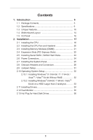
Contents 1. Introduction 5 1.1 Package Contents 5 1.2 Specifications 6 1.3 Unique Features 10 1.4 Motherboard Layout 14 1.5 I/O Panel 16 2. Installation 17 2.1 Installing the CPU 18 2.2 Installing the CPU Fan and Heatsink 20 2.3 Installing Memory Modules (DIMM 21 2.4 Expansion - ASRock H61TM-ITX | User Manual - Page 4
3.4.6 Intel(R) Smart Connect Technology 56 3.4.7 Super IO Configuration 57 3.4.8 ACPI Configuration 58 3.4.9 USB Configuration 60 3.4.10 Trusted Computing 61 3.5 Tool 62 3.6 Hardware Health Event Monitoring Screen 64 3.7 Boot Screen 65 3.8 Security Screen 67 3.9 Exit Screen - ASRock H61TM-ITX | User Manual - Page 5
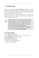
about the model you are using. www.asrock.com/support/index.asp 1.1 Package Contents ASRock H61TM-ITX Motherboard (Thin Mini-ITX Form Factor: 6.7-in x 6.7-in, 17.0 cm x 17.0 cm) ASRock H61TM-ITX Quick Installation Guide ASRock H61TM-ITX Support CD 2 x SATA Data Cables (Optional) 1 x SATA 1 to - ASRock H61TM-ITX | User Manual - Page 6
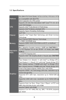
17.0 cm (Compatible with Mini-ITX) Solid Capacitors for CPU power Supports 3rd and 2nd Generation Intel® CoreTM i7 / i5 / i3 in LGA1155 Package Supports Intel® Turbo Boost 2.0 Technology Supports Intel® K-Series unlocked CPU Supports Hyper-Threading Technology Intel® H61 Supports Intel® Rapid Start - ASRock H61TM-ITX | User Manual - Page 7
Ports 1 x RJ-45 LAN Port with LED (ACT/LINK LED and SPEED LED) HD Audio Jacks: Front Speaker / Microphone 2 x SATA2 3.0 Gb/s connectors, support NCQ, AHCI and Hot Plug 1 x CIR header 1 x COM port header 1 x HDMI_SPDIF header 1 x LVDS connector 1 x LPC Debug header 1 x Home Theater PC header - ASRock H61TM-ITX | User Manual - Page 8
® 64-bit operating systems do not have such limitations. You can use ASRock XFast RAM to utilize the memory that Windows® cannot use. 2. PCIE 3.0 is only supported with Intel® Ivy Bridge CPU. With Intel® Sandy Bridge CPU, it only supports PCIE 2.0. 3. Intel® HD Graphics Built-in Visuals and the VGA - ASRock H61TM-ITX | User Manual - Page 9
WARNING Please realize that there is a certain risk involved with overclocking, including adjusting the setting in the BIOS, applying Untied Overclocking Technology, or using third-party overclocking tools. Overclocking may affect your system's stability, or even cause damage to the components and - ASRock H61TM-ITX | User Manual - Page 10
to improve efficiency when the CPU cores are idle without sacrificing computing performance. In XFast RAM, it fully utilizes the memory space that cannot be used under Windows® 32-bit operating systems. ASRock Instant Boot ASRock Instant Boot provides an efficient way to save energy, time, money - ASRock H61TM-ITX | User Manual - Page 11
the APP Charger driver, it makes your iPhone charge much quickly from your computer and up to 40% faster than before. ASRock APP Charger allows you to quickly charge many Apple devices simultaneously and even supports continuous charging when your PC enters into Standby mode (S1), Suspend to RAM - ASRock H61TM-ITX | User Manual - Page 12
regaining power. Please note that BIOS files need to be placed in the root directory of your USB disk. Only USB 2.0 ports support this feature. ASRock OMG (Online Management Guard) Administrators are able to establish an internet curfew or restrict internet access at specified times via OMG. You - ASRock H61TM-ITX | User Manual - Page 13
takes less than 1.5 seconds to logon to Windows 8 from a cold boot. No more waiting! The speedy boot will completely change your user experience and behavior. ASRock Restart to UEFI Windows® 8 brings the ultimate boot up experience. The lightning boot up speed makes it hard to access the UEFI setup - ASRock H61TM-ITX | User Manual - Page 14
1.4 Motherboard Layout 14 - ASRock H61TM-ITX | User Manual - Page 15
3 USB 2.0 Header (USB8) 4 Chassis Fan Connector (CHA_FAN1) 5 Consumer Infrared Module Header (CIR1) 6 SATA2 Connector (SATA_0) 7 USB 2.0 Header (USB6_7) 8 Mini PCI Express Slot (MINI_PCIE1) 9 USB 3.0 Header (USB3_0_1) 10 SATA Power Connector (SATA_POW1) 11 Power LED Header (PLED1) 12 - ASRock H61TM-ITX | User Manual - Page 16
1.5 I/O Panel 1* DC Jack 2 USB 3.0 Ports (USB01) 3 DVI-I (DVI1) 4 eSATA Connector (eSATA1) 5** LAN RJ-45 Port 6 USB 2.0 Ports (USB23) 7 Front Speaker (Lime) 8 Microphone (Pink) 9 HDMI Port (HDMI1) * Please use a 19V power adaptor for the DC jack. This jack accepts dual barrel plugs - ASRock H61TM-ITX | User Manual - Page 17
This is a Thin Mini-ITX form factor motherboard. Before you install the motherboard, study the configuration of your chassis to ensure that the motherboard fits into it. Pre-installation Precautions Take note of the following precautions before you install motherboard components or change any - ASRock H61TM-ITX | User Manual - Page 18
2.1 Installing the CPU In order to provide the LGA 1155 CPU sockets more protection and make the installation process easier, ASRock has added a new protection cover on top of the load plate to replace the former PnP caps that were under the load plate. For the - ASRock H61TM-ITX | User Manual - Page 19
off by itself. Please save and replace the cover if the processor is removed. The cover must be placed if you wish to return the motherboard for after service. 19 - ASRock H61TM-ITX | User Manual - Page 20
CPU Fan and Heatsink This motherboard is equipped with 1155-Pin socket that supports Intel 1155-Pin CPUs. Please (CPU_FAN1, see p.14, No. 22). For proper installation, please kindly refer to the instruction manuals of your CPU fan and heatsink. Below is an example to illustrate the installation of - ASRock H61TM-ITX | User Manual - Page 21
notch on the DIMM matches the break on the slot. The DIMM only fits in one correct orientation. It will cause permanent damage to the motherboard and the DIMM if you force the DIMM into the slot at incorrect orientation. Step 2. Firmly insert the DIMM into the slot until the retaining - ASRock H61TM-ITX | User Manual - Page 22
is 1 PCI Express slot and 1 mini PCI Express slot on this motherboard. Mini-PCIE Slot: MINI_PCIE1 is used for mini PCIE cards. PCIE slots: The x4 seated on the slot. Fasten the card to the chassis with screws. PCIE1 slot supports Gen 3 speed. To run PCI Express in Gen 3 speed, please install an - ASRock H61TM-ITX | User Manual - Page 23
. STEP 2: Connect one end of the SATA data cable to the hard disk. STEP 3: Connect the other end of the SATA data cable to the motherboard's SATA2 connectors. Serial ATA2 Connectors (SATA_0: see p.14, No. 6) SATA_1 (SATA_1: see p.14, No. 2) SATA_0 These two Serial ATA2 (SATA2) connectors - ASRock H61TM-ITX | User Manual - Page 24
2.6 Power Connectors SATA Power Connector (SATA_POW1) (see p.14, No. 10) Please connect a SATA power cable. 24 - ASRock H61TM-ITX | User Manual - Page 25
the power switch. RESET (Reset Switch): Connect to the reset switch on the chassis front panel. Press the reset switch to restart the computer if the computer freezes and fails to perform a normal restart. PLED (System Power LED): Connect to the power status indicator on the chassis front panel. The - ASRock H61TM-ITX | User Manual - Page 26
14, No. 7) Besides two default USB 2.0 ports on the I/O panel, there are three USB 2.0 headers and one USB port on this motherboard. Each USB 2.0 header can support two USB 2.0 ports. (4-pin USB8) (see p.14, No. 3) USB 3.0 Header (19-pin USB3_0_1) (see p.14, No. 9) Consumer Infrared Module Header - ASRock H61TM-ITX | User Manual - Page 27
allows convenient connection and control of audio devices. 1. High Definition Audio supports Jack Sensing, but the panel wire on the chassis must support HDA to function correctly. Please follow the instructions in our manual and chassis manual to install your system. 2. If you use an AC'97 audio - ASRock H61TM-ITX | User Manual - Page 28
state or S5 state (power off). Please connect a fan cable to the fan connector and match the black wire to the ground pin. Though this motherboard provides a 4-Pin CPU fan (Quiet Fan) connector, 3-Pin CPU fans can still work even without fan speed control. If you plan to connect a 3-Pin CPU - ASRock H61TM-ITX | User Manual - Page 29
HDMI_SPDIF Header (2-pin HDMI_SPDIF1) (see p.14, No. 25) Backlight & Amp Volume Control Header (8-pin BLT_VOL1) (see p.14, No. 17) Digital MIC Header (5-pin DMIC1) (see p.14, No. 24) Home Theater PC Header (7-pin HTPC1) (see p.14, No. 29) This header provides SPDIF audio output to HDMI VGA cards, - ASRock H61TM-ITX | User Manual - Page 30
LPC Debug Header (13-pin LPC1) (see p.14, No. 30) PIN Signal Name PIN Signal Name 14 +3V 13 No pin 12 +3V 11 +3V 10 GND 9 GND 8 LAD3 7 LAD2 6 LAD1 5 LAD0 4 LFRAME# 3 RESET# 2 GND 1 CLK 30 - ASRock H61TM-ITX | User Manual - Page 31
reset the system parameters to default setup, please turn off the computer and unplug the power cord from the power supply. After action. Please be noted that the password, date, time, user default profile, 1394 GUID and MAC address will be cleared only if the CMOS battery is removed. Backlight - ASRock H61TM-ITX | User Manual - Page 32
2.10 Operating System Setup This motherboard supports various Microsoft® Windows® operating systems: 8 / 8 64-bit / 7 / 7 64-bit / VistaTM / VistaTM 64-bit / XP / XP 64-bit. Because motherboard settings and hardware options vary, use the setup procedures in this chapter for general reference only. - ASRock H61TM-ITX | User Manual - Page 33
2.10.2 Installing Windows® 8 64-bit / 7 64-bit / VistaTM 64-bit on a HDD Larger than 2 terabytes (2TB) without RAID This motherboard adopts UEFI BIOS that allows Windows® OS to be installed on a large size HDD (>2TB). Please make sure to use Windows® VistaTM 64-bit (with - ASRock H61TM-ITX | User Manual - Page 34
necessary drivers and useful utilities that enhance the motherboard's features. 2.11.1 Running The Support CD To begin using the support CD, insert the CD into your CD-ROM drive. The CD automatically displays the Main Menu if "AUTORUN" is enabled in your computer. If the Main Menu does not appear - ASRock H61TM-ITX | User Manual - Page 35
VGA cards to this motherboard. This motherboard also provides independent display controllers for HDMI, DVI and LVDS to support dual VGA output so 't installed the VGA driver yet, please install it from our support CD and restart your computer. HDMI, DVI and LVDS monitors cannot all be enabled at - ASRock H61TM-ITX | User Manual - Page 36
13 Hot Plug for Hard Disk Drives This motherboard supports Hot Plug for SATA2 in AHCI mode. What been installed into the HDD. Hot Plug Operation Guide Before you process Hot Plug, please read this operation guide and check the cable accessories from the motherboard gift box pack below. A. 7-pin SATA - ASRock H61TM-ITX | User Manual - Page 37
SATA drivers are installed properly. The latest SATA drivers are available on our support website: www.asrock.com 6. Make sure to use the SATA power cable & data cable from our motherboard package. 7. Please follow the instructions step by step to reduce the risk of HDD crash or data loss. 37 - ASRock H61TM-ITX | User Manual - Page 38
to Hot Plug an HDD: Please follow the instructions below to process Hot Plug. Improper procedures will cause the HDD damage and data loss. Step 1 Please connect the SATA power Step 2 Connect the SATA data cable cable's 1x4-pin end (White) to to the motherboard's SATA the power supply's 1x4-pin - ASRock H61TM-ITX | User Manual - Page 39
How to Hot Unplug an HDD: Please follow the instructions below to process Hot Unplug. Improper procedures will cause the HDD damage and data loss. Step 1 Unplug the SATA data cable from the HDD's side. Step 2 Unplug the SATA 15-pin power cable connector (Black) from the HDD's side. 39 - ASRock H61TM-ITX | User Manual - Page 40
explains how to use the UEFI SETUP UTILITY to configure your system. The UEFI chip on the motherboard stores the UEFI SETUP UTILITY. You may run the UEFI SETUP UTILITY when you start up the computer. Please press or during the Power-On-Self-Test (POST) to enter the UEFI - ASRock H61TM-ITX | User Manual - Page 41
3.1.2 Navigation Keys Use < > key or < > key to choose among the selections on the menu bar, and use < > key or < > key to move the cursor up or down to select items, then press to get into the sub screen. You can also use the mouse to click your required item. Please check the following - ASRock H61TM-ITX | User Manual - Page 42
3.2 Main Screen When you enter the UEFI SETUP UTILITY, the Main screen will appear and display the system overview. Active Page on Entry This allows you to select the default page when entering the UEFI setup utility. 42 - ASRock H61TM-ITX | User Manual - Page 43
CPU Ratio Use this to change the ratio value of this motherboard. Intel SpeedStep Technology Intel SpeedStep technology is Intel's power [Enabled]. This item will be hidden if the current CPU does not support Intel SpeedStep technology. Please note that enabling this function may reduce CPU voltage - ASRock H61TM-ITX | User Manual - Page 44
is [Auto]. GT OverClocking Support Use this to enable or disable GT OverClocking Support. The default value is [ motherboard will detect the memory module(s) inserted and assign the appropriate frequency automatically. DRAM Configuration DRAM tCL Use this to change CAS# Latency (tCL) Auto/Manual - ASRock H61TM-ITX | User Manual - Page 45
settings. The default is [Auto]. DRAM tWTR Use this to change Write to Read Delay (tWTR) Auto/Manual settings. The default is [Auto]. DRAM tRTP Use this to change Read to Precharge (tRTP) Auto/Manual settings. The default is [Auto]. DRAM tFAW Use this to change Four Activate Window (tFAW) Auto - ASRock H61TM-ITX | User Manual - Page 46
. The default is [Auto]. ODT NOM (CHA) Use this to change ODT (CHA) Auto/Manual settings. The default is [Auto]. ODT NOM (CHB) Use this to change ODT (CHB) Auto/Manual settings. The default is [Auto]. MRC Fast Boot Use this to enable or disable MRC Fast Boot. The default is [Enabled - ASRock H61TM-ITX | User Manual - Page 47
Configuration, South Bridge Configuration, Storage Configuration, Intel(R) Rapid Start Technology, Intel(R) Smart Connect Technology, Super IO Configuration, ACPI Configuration, USB Configuration and Trusted Computing. Setting wrong values in this section may cause the system to malfunction. 47 - ASRock H61TM-ITX | User Manual - Page 48
Technology To enable this feature, a computer system with an Intel processor that supports Hyper-Threading technology and an operating system processors support the Halt State (C1). C1 state is supported through the native processor instructions HLT and MWAIT and requires no hardware support from - ASRock H61TM-ITX | User Manual - Page 49
prevent data pages from being used by malicious software to execute codes. This option will be hidden if the current CPU does not support No-Excute Memory Protection. Intel Virtualization Technology When this option is set to [Enabled], a VMM (Virtual Machine Architecture) can utilize the additional - ASRock H61TM-ITX | User Manual - Page 50
3.4.2 North Bridge Configuration Primary Graphics Adapter This allows you to select [Onboard] or [PCI Express] as the primary graphics adapter. The default value is [PCI Express]. PCIE1 Link Speed This allows you to select PCIE1 Link Speed. Share Memory This allows you to configure share memory. The - ASRock H61TM-ITX | User Manual - Page 51
Volume Control Use this to fine tune the desired volume. 51 - ASRock H61TM-ITX | User Manual - Page 52
the Wireless function. Radio Controller This allows you to enable or disable the Radio Controller. Deep Sleep Mobile platforms support Deep S4/S5 in DC only and desktop platforms support Deep S4/S5 in AC only. Configuration options: [Disabled], [Enabled in S5] and [Enabled in S4 and S5]. Restore - ASRock H61TM-ITX | User Manual - Page 53
when the power recovers. If [Power On] is selected, the AC/power resumes and the system starts to boot up when the power recovers. Good Night LED Use this to enable or disable the Power LED and LAN LED. 53 - ASRock H61TM-ITX | User Manual - Page 54
for SATA2_0 and SATA2_1 ports. Configuration options: [IDE Mode] and [AHCI Mode]. The default value is [AHCI Mode]. AHCI (Advanced Host Controller Interface) supports NCQ and other new features that will improve SATA disk performance but IDE mode does not have these advantages. SATA Aggressive Link - ASRock H61TM-ITX | User Manual - Page 55
5-6 seconds. The default is [Enabled]. Entry After Select a time to enable RTC wake timer at S3 entry. The default is [10 minutes]. Active Page Threshold Support This allows you to enable or disable Active Page Threshold - ASRock H61TM-ITX | User Manual - Page 56
or disable Intel(R) Smart Connect Technology. Intel(R) Smart Connect Technology keeps your e-mail and social networks, such as Twitter, Facebook, etc. updated automatically while the computer is in sleep mode. The default is [Enabled]. 56 - ASRock H61TM-ITX | User Manual - Page 57
3.4.7 Super IO Configuration Serial Port Use this to enable or disable the onboard serial port. Serial Port Address Use this to set the address for the onboard serial port. Configuration options: [3F8h / IRQ4] and [3E8h / IRQ4]. 57 - ASRock H61TM-ITX | User Manual - Page 58
detect or disable Suspend-toRAM. Select [Auto] to enable if the OS supports it. Check Ready Bit Use this to enable or disable Check Ready Bit ]. Please set this option to [Enabled] if you plan to use this motherboard to submit Windows® VistaTM certification. PCI Devices Power On Use this to enable - ASRock H61TM-ITX | User Manual - Page 59
system. CSM Please disable CSM when Fast Boot is enabled. The default value is [Enabled]. 59 - ASRock H61TM-ITX | User Manual - Page 60
USB 3.0 controller. Legacy USB Support Use this to select legacy support for USB devices. There are [Enabled] - Enables support for legacy USB. [Auto] - Enables legacy support if USB devices are Linux OS. Legacy USB 3.0 Support Use this to enable or disable legacy support for USB 3.0 devices. The - ASRock H61TM-ITX | User Manual - Page 61
3.4.10 Trusted Computing Security Device Support Use this to enable or disable BIOS support for security devices. 61 - ASRock H61TM-ITX | User Manual - Page 62
3.5 Tool OMG (Online Management Guard) Administrators are able to establish an internet curfew or restrict internet access at specified times via OMG. You may schedule the starting and ending hours of internet access granted to other users. In order to prevent users from bypassing OMG, guest - ASRock H61TM-ITX | User Manual - Page 63
OS. Please note that you must be running on a DHCP configured computer in order to enable this function. Network Configuration Use this to configure internet connection settings for Internet Flash. User Defaults You are allowed to load - ASRock H61TM-ITX | User Manual - Page 64
Monitoring Screen This section allows you to monitor the status of the hardware on your system, including the parameters of the CPU temperature, motherboard temperature, fan speed and voltage. CPU Fan 1 Setting This allows you to set CPU fan 1's speed. Configuration options: [Full On] and [Automatic - ASRock H61TM-ITX | User Manual - Page 65
boot settings and the boot priority. Fast Boot Fast Boot minimizes your computer's boot time. Configuration options: [Disabled] - Disable Fast Boot. [Fast windows. 3. If you are using an external graphics card, the VBIOS must support UEFI GOP in order to boot. Boot From Onboard LAN Use this to - ASRock H61TM-ITX | User Manual - Page 66
after boot-up. Full Screen Logo Use this item to enable or disable OEM Logo. The default value is [Enabled]. AddOn ROM Display Use this option to adjust AddOn ROM Display. If you enable the option "Full Screen Logo" - ASRock H61TM-ITX | User Manual - Page 67
3.8 Security Screen In this section you may set or change the supervisor/user password for the system. You may also clear the user password. Secure Boot Use this to enable or disable Secure Boot Control. The default value is [Disabled]. 67 - ASRock H61TM-ITX | User Manual - Page 68
3.9 Exit Screen Save Changes and Exit When you select this option the following message, "Save configuration changes and exit setup?" will pop out. Select [OK] to save changes and exit the UEFI SETUP UTILITY. Discard Changes and Exit When you select this option the following message, "Discard
-
 1
1 -
 2
2 -
 3
3 -
 4
4 -
 5
5 -
 6
6 -
 7
7 -
8
-
9
-
10
-
11
-
12
-
13
-
14
-
15
-
16
-
17
-
18
-
19
-
20
-
21
-
22
-
23
-
24
-
25
-
26
-
27
-
28
-
29
-
30
-
31
-
32
-
33
-
34
-
35
-
36
-
37
-
38
-
39
-
40
-
41
-
42
-
43
-
44
-
45
-
46
-
47
-
48
-
49
-
50
-
51
-
52
-
53
-
54
-
55
-
56
-
57
-
58
-
59
-
60
-
61
-
62
-
63
-
64
-
65
-
66
-
67
-
68
 |
 |
1
H61TM-ITX
User Manual
Version 1.0
Published November 2012
Copyright©2012 ASRock INC. All rights reserved.